


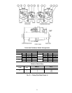
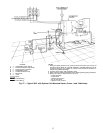
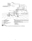
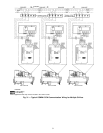
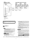
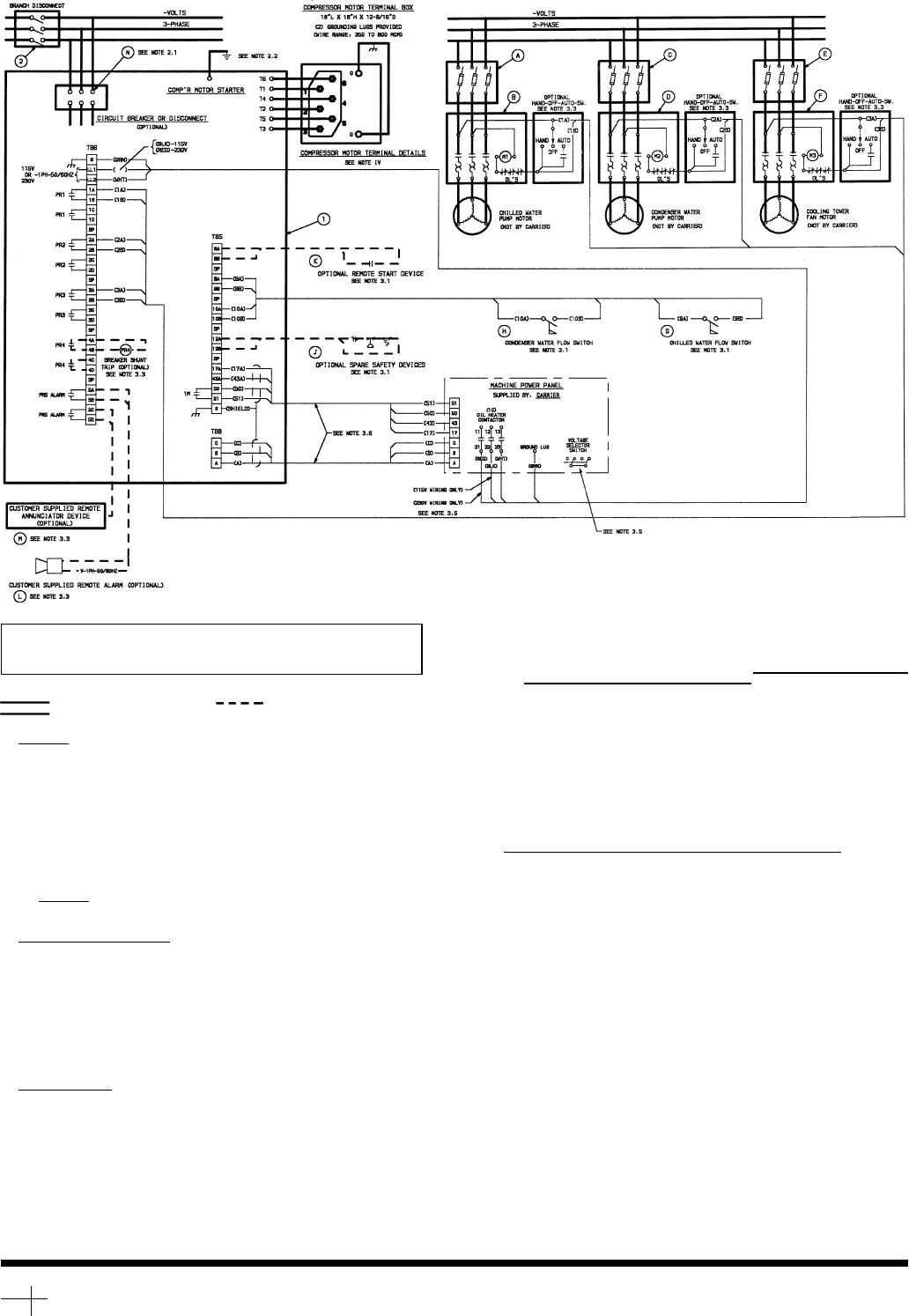
IMPORTANT: Wiring shown is typical and not intended to show detail
for a specific installation. Refer to certified field wiring diagrams for
additional information. Certified drawings are available upon request.
LEGEND
Required Power Wiring Options Wiring
Required Control Wiring
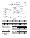
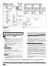
NOTES:
I. GENERAL
1.0 Startersshall bedesignedand manufacturedin accordancewithCarrier Engineer-
ing Requirement Z-375.
1.1 All field-supplied conductors, devices, field-installation wiring, and termination of
conductors and devices, must be in compliance with all applicable codes and job
specifications.
1.2 The routing of field-installed conduit and conductors and the location of field-
installed devices,must not interferewith equipment access orthe reading, adjust-
ing, or servicing of any component.
1.3 Equipment, installation, and all starting and control devices must comply with de-
tails in equipment submittal drawings and literature.
1.4 Contactsandswitchesareshown inthepositiontheywouldassumewiththe circuit
deenergized and the chiller shut down.
1.5 WARNING — Do not use aluminumconductors.
1.6 Installeris responsiblefor any damagecaused byimproper wiringbetween starter
and machine.
II. POWER WIRING TO STARTER
2.0 Powerconductor ratingmust meetminimum unitnameplate voltageand compres-
sor motor RLA(rated load amps).
When (3) conductors are used:
Minimum ampacity per conductor = 1.25 x compressorRLA
When (6) conductors are used:
Minimum ampacity per conductor = 0.721 x compressorRLA
2.1 Lug adapters may be required if installation conditions dictate that conductors be
sized beyond the minimum ampacity required. Contact starter supplier for lug
information.
2.2 Compressor motorand controls must begrounded by using equipmentgrounding
lugs provided inside starter enclosure.
III. CONTROLWIRING
3.0 Field suppliedcontrol conductors tobe at least18 AWG (AmericanWire Gage) or
larger.
3.1 Chilled water and condenser water flow switch contacts, optional remote start
devicecontactsandoptionalsparesafetydevicecontacts,musthave24vdcrating.
Max current is 60 ma, nominal current is 10 ma. Switches with gold plated
biurcated contacts are recommended.
3.2 Removejumperwirebetween12Aand12Bbeforeconnecting auxiliarysafeties be-
tween these terminals.
3.3 Pilotrelays cancontrol coolerand condenserpump andtower fanmotor contactor
coilloadsrated10ampsat115vacupto3ampsat600vac.Controlwiringrequired
forCarriertostartpumpsandtowerfanmotorsmustbeprovidedtoassuremachine
protection. If primary pump and tower fan motor control is by other means, also
provide a parallel means for control by Carrier. Do not use starter control trans-
former as the power source for pilot relayloads.
3.4 Do not route control wiring carrying 30 v or less within a conduit which has wires
carrying 50 v or higher or along sidewires carrying 50 v or higher.
3.5 Voltageselectorswitchinmachinepowerpanelisfactorysetfor115vcontrolpower
source. When 230 v control power source is used, set switch to 230 v
position.
3.6 Controlwiring cablesbetweenstarter andpowerpanel mustbeshielded withmini-
mum rating of 600 v, 80 C. Ground shield at starter.
3.7 VoltagetoterminalsLL1and LL2comesfromacontroltransformer inastarterbuilt
to Carrierspecifications. Do notconnect anoutside source ofcontrol power tothe
compressor motor starter (terminals LL1 and LL2). An outside power source will
producedangerousvoltageatthelinesideofthestarter,becausesupplyingvoltage
at the transformer secondary terminals produces input level voltage at the trans-
former primary terminals.
IV. POWER WIRING BETWEEN STARTERAND COMPRESSOR MOTOR
4.0 Lowvoltage (600v or less)compressor motorshave(6)
1
⁄
2
in. terminalstuds (lead
connectors notsuppliedby Carrier).Either 3or 6leadsmust berun betweencom-
pressor motor and starter, depending ontype of motor starter employed. If only 3
leads arerequired, jumpermotor terminalsasfollows: 1to 6,2 to4, 3to 5.Center
tocenterdistancebetweenterminalsis2.73inches.Compressormotorstartermust
have nameplate stamped as to conforming with Carrierrequirement ‘‘Z-375.’’
4.1 Whenmore thanone conduitis usedto runconductors fromstarter tocompressor
motor terminal box, one conductor from each phase must be in each conduit, to
prevent excessive heating. (e.g., conductors to motor terminals 1, 2 and 3 in one
conduit, and these to 4, 5 and 6in another.)
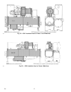
4.2 Compressor motor power connections can be made through top, bottom, or right
sideof compressormotorterminalbox byrotatingtheterminal boxandusingholes
cutbycontractortosuitconduit.Flexibleconduitshouldbeusedforthelastfewfeet
tothe terminalboxforunit vibrationisolation.Useof stressconesor12 conductors
larger than 500 MCM may require an oversize (special) motor terminal box (not
supplied by Carrier). Lead connections between 3-phase motors and their
starters must not be insulated until Carrier personnel have checked compressor
rotation.
4.3 Compressormotorframeto begroundedinaccordance withtheNationalElectrical
Code (NFPA-70) and applicablecodes. Means forgrounding compressor motoris
(2)Thomas andBetts pressureconnectorsfor 350to 800MCMwire, suppliedand
located in the back upper and lower right side corners of the compressor motor
terminal box.
4.4 Donot allow motorterminals to supportweight of wirecables. Use cablesupports
and strain reliefs as required.
4.5 Usebackupwrenchwhentighteningleadconnectorstomotorterminalstuds.Torque
to 10-15 lb-ft maximum.
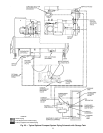
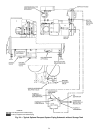
Fig. 35 — 23XL Typical Field Wiring with Free-Standing Starter (Frame 1 and 2 Machines Shown)
Copyright 1994 Carrier Corporation
Manufacturer reserves the right to discontinue, or change at any time, specifications or designs without notice and without incurring obligations.
Book 2
Tab 5e
PC 211 Catalog No. 532-303 Printed in U.S.A. Form 23XL-2SI Pg 34 796 9-94 Replaces: 23XL-1SI
→