


Operator’s Manual P/N-260AOZ-A
______________________________________________________________________________
5
For Gas-Fired Steam Generators: Post in a prominent
location, instructions to be followed in the event the user
smells gas. This information shall be obtained by the
consulting the local gas supplier.
Install a sediment trap (drip leg) in the gas supply line, and
then connect gas supply piping to the boiler gas valve
piping. GAS-FIRED EQUIPMENT IS DESIGNED FOR
INSTALLATION ONLY IN NONCOMBUSJJBLE
LOCATIONS. THIS INCLUDES THE FLOOR-INC THAT
WILL BE DIRECTLY UNDER THE EQUIPMENT Location,
plumbing size, and pressure data are shown on the
specification sheet. Boilers rated at less than 225,000 Btu
require 3/4-inch 'PS gas supply piping, and boilers rated at
225,000 Btu or more require 1-inch II'S gas supply piping.
Natural gas pressure must be between 4" -14" water
column and LP gas supply pressure must be between 12"
- 14" water column. NEVER EXCEED 14" WATER
COLUMN (1/2 psi) GAS PRESSURE. If the gas supply
pressure exceeds 14" water column, a pressure-regulating
valve must be installed in the gas plumbing to reduce the
gas pressure to less than 14" water column. Installation
must be in accordance with local codes, or in the absence
of local codes, with the National Fuel Gas Code, ANSI
Z223.1-1984. Installation in Canada must be in ac-
cordance with Installation codes for Gas Burning Appli-
ances and Equipment B149.1 and B149.2. Use a gas pipe
joint compound, which is resistant to LP gas. Turn the gas
valve control knob to ON (the word "on" the knob will be
opposite the index on the valve's body). Test all pipe joints
for leaks with soap and water solutions. Never obstruct the
flow of combustion and ventilation air Observe all
clearance requirements to provide adequate air openings
into the combustion chamber. The appliance and it's indi-
vidual shutoff valve must be disconnected from the gas
supply piping system during any pressure testing of that
system at test pressures in excess of 14" water column
(1/2 psi or 3.45 k}'a). The appliance must be isolated from
the gas supply piping system at test pressures equal to or
less than 14" water column (1/2 psi or 3.45 kpa). A perma-
nent 115-volt electrical connection is required at the junc-
tion box. The junction box location is shown on the speci-
fication sheet. The installer must electrically ground the
unit.
For Electric-Powered Steam Generators: Connect
electric power: location and data are shown on the
specification sheet. Provide connection as required by the
unit, either directly to the single contactor, or to the
terminal block (when equipped with multiple contactors).
Electric supply must match power requirements specified
on the data plate inside the base cabinet. The copper
wiring size must be adequate to carry the required current
at the rated voltage. A separate fused disconnect switch
must be supplied and installed. The installer must
electrically ground the unit
For Steam Coil Steam Generators: Connect steam
supply piping to the input side of the steam coil. Location
and pressure data are shown on the specification sheet.
Incoming steam pressure must be regulated between 35
and 45 psi. A 3 /4inch strainer, equipped with a 20 mesh
stainless steel screen, must be supplied and installed at
the incoming steam connection
point. Flush the steam line
thoroughly before connecting it to the boiler. To ensure an
adequate volume of steam, the branch steam supply line
must be 3/~inch 'PS minimum. Connect the inverted
bucket trap to the outlet end of the steam coil. Pill the trap
with water before installing it. A permanent 115-volt
electrical connection is required at the junction box. The
junction box location is shown on the specification sheet.
The installer must electrically ground the unit.
For Direct-Steam Connected Steamers and Kettles:
Connect steam supply piping to the input side of the line
strainer. Location and pressure data are shown on the
specification sheet. Flush the steam line thoroughly before
connecting it to the steamer. To ensure an adequate
volume of steam, the branch steam supply line must be
3/4 inch 'PSI 'minimum. Direct-steam-connected kettles
require 1 /2-inch 'PS pipe if the kettle total capacity is 20
gallons or less, and 3/4-inch 'PS pipe if the total capacity
exceeds 20 gallons.) A permanent 115 volt electrical
connection is required at the junction box. The junction
box location is shown on the specification sheet. The
installer must electrically ground the unit
INSTALLATION CHECKS
Proper operation of the Cleveland Convection Steamer is
dependent upon proper installation. After the steamer has
been installed, a few quick checks could save
unnecessary service calls.
1. The unit must be level.
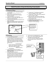
2. The Convection Steamer requires a cold water connec-
tion for proper efficient operation. DO NOT USE HOT
WATER. The cold water must be connected to the line
strainer, located at the front lower right of the steamer
base.
3. Check that the manual water supply valve is open.
4. Check all water supply lines and valves for leaks.
5. Check that the water supply pressure and water quality
meets the requirements of installation paragraphs.
6. On electrical units, verify that the supply voltage meets
the voltage requirements on the rating plate inside the
base cabinet and the voltage shown on the packing
slip. Verify that the unit is protected with a separate
fused disconnect and is properly grounded in
accordance with the National Electric Code.