


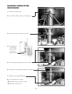
3. Remove Guard Bracket (A).
4. Pull Pressure Relief Valve (B) open to insure vessel
is not pressurized.
5. Remove Pressure Relief Valve (B).
6.
Replace Pressure Relief Valve (B) with Street Elbow (C).
7. Add distilled water (D) through the Street Elbow (C),
using a funnel if necessary. Refer to
Distilled Water
Requirements
chart for the proper amount required.
8. Apply a thread sealant (i.e. Teflon tape) to the
Pressure Relief Valve's (B) thread and replace.
9. Replace Guard Bracket (A).
10.
Restore power to unit at the fused disconnect switch.
11.
The kettle must now be vented. (Refer to the Kettle
Venting Instructions shown below).
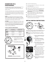
A. Remove
Guard
Bracket
B.
*
Remove
Pressure
Relief
Valve
C.
Attach Street
Elbow
D. Fill unit via Street Elbow
*Important-
Pull ring on Pressure Relief Valve
prior to removal to insure vessel is not pressurized.
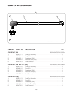
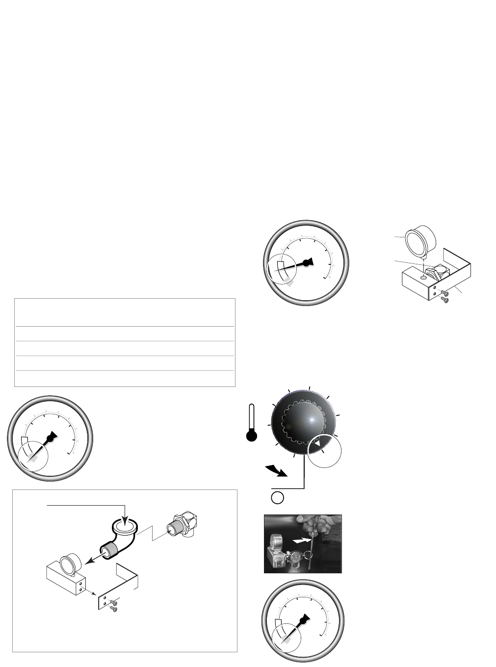
Pressure Relief Valve/Gauge Assembly Drawing
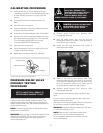
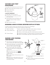
KETTLE VENTING INSTRUCTIONS
RESERVOIR FILL
PROCEDURES
The kettle's water level must be maintained at the proper level to
submerge the heater elements. Under normal operating
conditions, the sealed water reservoir should never require the
addition of water.
If the red "low water" light comes on during use (while the kettle is
in an upright position), the water level has reached a critically low
level. The low water protection control has automatically shut off
the heater elements. The following procedure must be completed
before further use:
NOTE: Have a qualified service technician repair the leakage
problem and add water to the unit. Ensure that the red "low water"
light is on when the kettle is upright. On tilting kettles, it is normal
for the red light to come on when the kettle is in a tilted position, as
the elements are not submerged in water at this point.
CAUTION: Only a mixture of distilled water and rust inhibitor should
be used when adding water to a partially filled water reservoir. Local
tap water conditions may cause kettle damage which is not covered
under warranty. Rust inhibitor is purchased locally. Read directions
and do not exceed manufacturer's recommendation (excessive rust
inhibitor can also cause solidification).
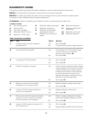
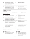
DISTILLED WATER REQUIREMENTS
1. Ensure kettle is at room
temperature and pressure
gauge showing zero or less
pressure.
2. Shut off power to the kettle at
the fused disconnect switch.
When Red “Low Water When the Reservoir is
Kettle Light” comes Completely Empty,
Capacity on, add Distilled Water Add Distilled Water
3 gallon 50 ounces 120 ounces
6 gallon 70 ounces 160 ounces
12 gallon 120 ounces 2 gallon
20 gallon 1 gallon 3 gallon
1. Remove guard bracket from
pressure relief valve/gauge
assembly.
2. Turn kettle ON and set
Temperature Control to 10
(Max.), heat the empty kettle
until unit cycles off.
3. Vent kettle by pulling safety
valve ring 8-10 times in short
2-3 second blasts with a 5
second interval between
pulls.
NOTE: If unit cycles ON, stop
venting and wait for kettle to
cycle OFF before continuing.
4. Turn kettle OFF. Add cold
water to kettle until its surface
temperature is below 100°F.
The pressure gauge needle
should be in the green zone,
indicating a vacuum in the
kettle’s jacket.
5. Replace guard bracket from
pressure relief valve/gauge
assembly.
2
3
5
6
7
8
9
1
4
10
OFF
50
0
100
150
200
250
300
350
400
40
50
60
0
10
20
30
psi
kPa
V
E
N
T
A
I
R
50
0
100
150
200
250
300
350
400
40
50
60
0
10
20
30
psi
kPa
V
E
N
T
A
I
R
50
0
100
150
200
250
300
350
400
40
50
60
0
10
20
30
psi
kPa
V
E
N
T
A
I
R
18
Guard
Bracket
Pressure
Gauge
Pressure
Relief
Valve
The following venting procedure
should be followed when the
Vacuum/Pressure Gauge needle
is in the "VENT AIR" zone:
NOTE: Check for and eliminate leaks prior to venting
(See Repairing Leaks in Steam Jacketed Kettle Fittings
on page 19).