


8
Parts List
2 Grates
1 Small Stack Burner Cap
1 Small Stack Burner Ring
2 Large Stack Burner Caps
2 Large Stack Burner Rings
1 Crown Burner Cap
1 Crown Burner Ring
1 Crown Burner Head
1 GlideRack™ Oven Rack
2 Standard Size Racks
•
•
•
•
•
•
•
•
•
•
4 Knobs
Anti-tip Bracket w/Screws
Meat Probe
Griddle
Wok Ring
Stainless Steel Cleaner
Lens Pry Stick
Literature Kit
Ignitor Cleaning Brush
Broiler Pan/Grill
•
•
•
•
•
•
•
•
•
•
See the use and care manual for a list of optional parts and
accessories.
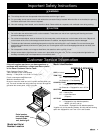
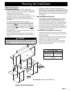
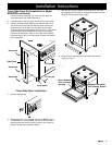
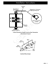
NOTE: The range also includes a
thread ring removal tool
(Part # 101539) for the crown burner.
It is tie wrapped in place behind the
right side of the kick panel when the
range is shipped from the factory.
Leave it in place unless the spill tray
needs to be removed for service.
Return it after use so that it is
available if needed in the future.
Preparing for Installation
WARNING
If the gas or electric service provided does not meet the
product specifications, do not proceed with the installation.
Call the dealer, the gas supplier or a licensed electrician.
Before installing the range, you must locate and secure the
anti-tip bracket to the floor.
Be sure that the unit is not connected to gas or power
before proceeding with the following sections.
•
•
•
IMPORTANT: Within the Commonwealth of Massachusetts, this
appliance must be installed by a licensed plumber or gas fitter.
NOTE: When installing a backguard, always install it before
sliding the range into place. See page 9.
Unpack the Range
Unpack the range and verify that all required parts have been
provided. If any item is missing or damaged, please contact
your dealer immediately. Do not install a damaged or incomplete
appliance. The customer must report cosmetic issues within 30
days of installation.
Planning the Installation
Thread Ring Removal
Tool Location
Installation Instructions
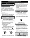
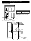
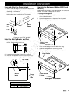
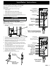
Non-Combustible
Rear Wall
Combustible Side
Wall Above Range
Countertop
Opening
29 1/4” (743mm)
30 1/16” (764mm)
Cabinet
Opening
23 9/16”
(598mm)
7/16”
(11mm)
10” Min.
(254mm)
Both Sides
1”
(25mm)
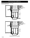
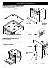
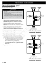
Rear Wall
Countertop
Opening
29 1/4” (743mm)
ERV Opening
27 7/8” (708mm)
Minimum Cabinet depth: 27 1/8” (688mm)
Minumum Countertop depth: 28 1/8” (714mm)
30 1/16” (764mm)
Cabinet
Opening
24 1/16”
(611mm)
2 13/16” (71mm)
1”
(25mm)
1/4” Min.
(6mm)
Combustible Side
Wall Above Range
10” Min.
(254mm)
Both Sides
Notes on Self-Rimming Installations:
The above specifications assume a standard 24 inch cabinet
depth and 25 inch countertop depth.
When sliding the range into position, the range stops
when the rear of the control panel hits the 1” notch in the
countertop, leaving a 7/16” gap between the rear trim and the
wall behind.
•
•
Cabinet Cutout Dimensions
Self Rimming Installation
Cabinet Cutout Dimensions
Self Rimming Installation
with ERV Raised Vent
Notes on Self-Rimming Installations with ERV:
The top and rear trim for the ERV trim kit are 1/2” deeper
than the trim for installations without an ERV to allow the
range to clear the ERV.
When sliding the range into position, the range stops when
the rear of the control panel hits the 1” notches in the front of
the countertop.
•
•
NOTE: If installing in a deeper countertop or installing a custom backguard, you may install the available 3” side
panel kit to allow for custom countertop notches of 1 to 4 inches.