


18
Installation Instructions
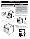
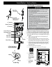
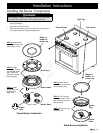
Notch on bottom
of hinge
Lower lip
of hinge
receptacle
Door Installation
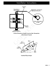
Final Installation
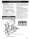
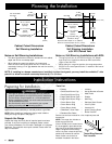
Peel the protective plastic coating off of the range, including
the range door.
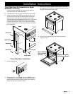
Adjust the range legs to the desired height.
Carefully slide the range into position in the cutout. The rear
anti-tip leg should engage the anti-tip bracket.
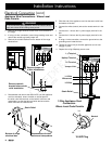
Re-installing the Oven Door(s)
WARNING
To avoid personal injury or damage to the door from it falling off
its hinges:
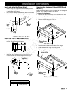
Make sure that the notch on the bottom of each hinge rests
on top of the lower lip of each hinge receptacle before
attempting to open the oven door.
Rotate the hinge locks toward the front of the range
immediately after installation of the door.
•
•
Grasp the oven door on opposite sides and hold it at a 15°
angle from the front of the oven. Slide the hinges into the
hinge openings, resting the bottom of the hinge arms on the
hinge receptacles. Continue to hold the door at a 15° angle
with one hand while pushing in on each of the bottom corners
of the door. Push until the notch on the bottom of each hinge
slips over the lower lip of each hinge receptacle.
Lower the door to the fully opened position.
Rotate the two hinge locks toward the oven.
Slowly and carefully open and close the door completely to
ensure that it is properly installed.
Remove any packaging from inside the oven(s).
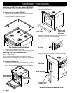
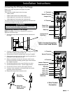
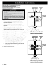
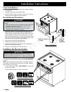
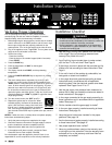
Installing the Burner Knobs
CAUTION
Installing the range knobs in the wrong position may result in
damage to the griddle included with the range. The knobs for
the right burners are marked with the maximum griddle settings.
There are two (2) different types of knobs supplied with the range.
The knobs for the right burners have the words “MAX GRIDDLE”
on them.
NOTE: When installing the knobs, align the “D-shaped” opening
on the back of the knob with the end of the valve shaft. Carefully
push the knob on until it stops.
Put the knobs with the words “MAX GRIDDLE” on them onto
the right valve shafts.
Put the remaining knobs on the left valve shafts
1.
2.
3.
1.
2.
3.
4.
5.
•
•
Icons on Left Burner Knobs
Icons on Right Burner Knobs