


24G SERIES FLATBOTTOM GAS FRYERS
CHAPTER 1: SERVICE PROCEDURES
1-14
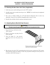
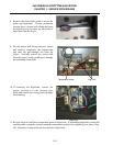
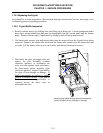
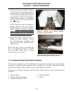
2. Remove blower assembly by removing
four screws (two screws securing the flue
outlet to the firebox, and two screws
securing the blower inlet housing to the
firebox). Pull the assembly out of the slot
and lower to the side. Do not remove the
electrical connections at this time.
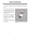
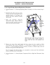
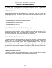
3. If replacing air prover switch, remove
junction box cover, mark and disconnect
wiring to the switch. Remove screws
securing the switch to the junction box,
and then remove the switch from the
blower housing. Install new switch,
ensuring the switch flap is correctly
positioned in the blower housing.
Reattach wires removed from old switch
and replace box cover.
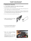
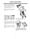
4. If replacing blower, remove junction box
cover, mark and disconnect each wire, and
remove conduit fitting from junction box.
Reinstall conduit fitting on new blower
and reconnect wiring. Replace box cover.
5. Reverse steps 1 – 4 to reinstall blower
assembly.
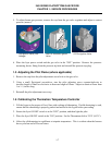
After removing screws (arrows), remove blower
assembly from firebox by pulling outward.
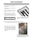
Blower junction box wiring. Mark wire locations
before disconnecting each wire.