


24G SERIES FLATBOTTOM GAS FRYERS
CHAPTER 1: SERVICE PROCEDURES
1-16
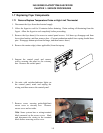
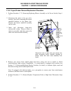
1.7.6.2 Frypot/Firebox Removal/Replacement Procedure
1. Perform Procedure 1.7.5, Removing/Replacing Blower Assembly or Air Prover Switch, Steps 1
– 4.
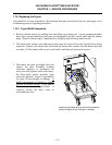
2. Disconnect the union at the gas valve.
Remove four bolts connecting the burner
manifold brackets to the burner box.
Remove the burner manifold assembly
and set aside.
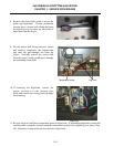
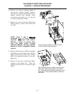
3. Mark and disconnect drain-valve
microswitch wiring. Remove elbow or
drain-tee assembly, and then remove the
drain valve/microswitch assembly.
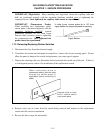
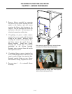
4. Remove two screws from control panel and lower, using care not to stretch or distort
switch/indicator light wiring (if applicable). If control panel is equipped with switches (see
Section 1.7.2, Removing/Replacing Rocker Switches, for detail), or indicator lights, mark and
disconnect wiring and set control panel aside.
Note: If equipped with indicator lights, use a pin-pusher to remove pins from main-harness
connector, and then remove control panel.
5. Perform Procedure 1.7.1, Remove/Replace Temperature Probe or High-Limit Thermostat, Steps
7 – 11.
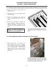
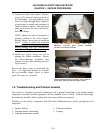
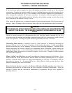
Disconnect union at gas valve and remove four
bolts connecting burner manifold brackets to
firebox, elbow and drain valve assembly from
frypot.
Remove drain
elbow and
drain valve
assembly from
the frypot.
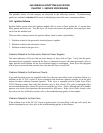
Disconnect
union at gas
valve and
remove four
bolts (two per
side) to
remove burner
manifold.