


24G SERIES FLATBOTTOM GAS FRYERS
CHAPTER 1: SERVICE PROCEDURES
1-2
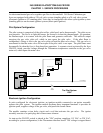
An electromechanical gas valve regulates gas flow to the manifold. 24G Series Flatbottom gas
fryers are equipped with either a 120-volt valve system (standing pilot) or a 24-volt valve system
(electronic ignition or CE standing pilot). Units may be configured with either a pilot ignition system
(standing pilot) or an electronic ignition system (direct spark ignition).
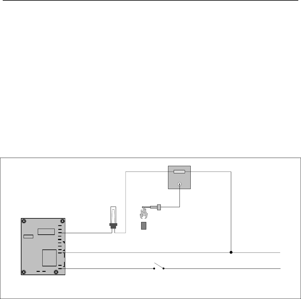
Pilot System Configuration
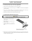
The pilot system is comprised of the pilot orifice, pilot hood, and a thermocouple. The pilot serves
two purposes. The first is to light the burner, the second is to heat the thermocouple. In operation,
the thermocouple is in contact with the pilot flame and generates millivolts. The millivolt output
energizes the gas valve pilot coil, which in turn opens the pilot valve. If the pilot flame is
extinguished, voltage is lost to the gas valve pilot coil and the pilot valve closes. The gas valve is
constructed so that the main valve will not open if the pilot valve is not open. The pilot flame must
be manually lit when the fryer is first placed into operation. A separate circuit, activated by the fryer
ON/OFF switch, provides voltage through the Thermatron temperature controller to the gas valve
main coil, which opens the main valve.
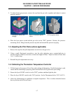
Thermatron Temperature
Controller
High-Limit
Thermostat
Line Voltage
Line Voltage
The Pilot System
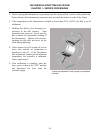
120V
MELT CYCLE DISABLE
6
5
1
AC1
3
AC2 3A 2A
7
8
9
1A
EXT POT
PROBE
10
11
2
COM
RELAY
NO
12 13
NC
14
Thermocouple
Pilot Coil
Main Coil
Gas
Valve
Pilot
ON/
OFF
Switch
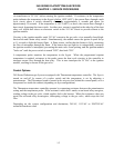
Electronic Ignition Configuration
In units configured for electronic ignition, an ignition module connected to an ignitor assembly
replaces the pilot system. The ignition module performs three important functions: it provides an
ignition spark, supplies voltage to the gas valve, and proofs the burner flame.
The module contains a time delay circuit and a coil that activates the gas valve. The ignitor
assembly consists of a spark plug and a flame sensor element.
At start-up the ON/OFF switch is placed in the "ON" position, supplying 115 VAC or 230 VAC,
according to system configuration, to the Thermatron interface board. The voltage is stepped down