Part # MPSM07 (03/24/08) Page 11
INSTALLATION
It is the responsibility of the purchaser to ensure the oven is
installed in a manner to meet all local codes. In the absence
of local codes, applicable national codes are referenced in this
booklet. In the case of discrepancy between the information
in this booklet and local codes, it is recommended you
consult your local inspector(s). This appliance meets or
exceeds all applicable regulations and standards in eect on
its date of manufacture.
Location
The importance of the proper installation of Commercial
Gas Cooking Equipment cannot be over stressed. Proper
performance of the equipment is dependent, in great part,
on the compliance of the installation with the manufacturer’s
specications. Installation must conform to local codes or, in
the absence of local codes, with the National Fuel Code, ANSI
Z223.1, Natural Gas Installation Code, CAN/CGA-B149.1, or the
Propane Installation Code, CAN/CGA-B149.2, as applicable.
Wall Clearance
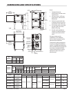
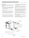
This oven, single or stacked, must be installed with adequate
clearance to combustible and non-combustible walls.
Sides: 1 inch [25 mm]
Back: 3 inches [76 mm] for gas ovens, and
6 inches [152 mm] for electric ovens.
Garland recommends that a one inch clearance be
maintained between this oven and any other cooking
appliance.
Garland recommends that this oven not be installed with a
broiler or open burner appliance immediately adjacent to the
right side.
Each appliance shall be located with respect to building
construction and other equipment so as to permit access to
the appliance. Such access and clearance may be necessary
for servicing and cleaning.
GAS CONNECTIONS
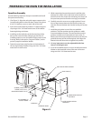
The type of gas for which the oven is equipped is stamped on
the data rating plate. It is located inside the lower front trim
cover. Connect an oven stamped “NAT” to natural gas only.
Connect an oven stamped “PRO” to propane gas only.
If the oven is being installed into a new location, have gas
authorities check the meter size and piping to assure the supply
line has a sucient amount of gas pressure to operate the oven.
If the oven is a replacement or additional appliance to an
existing installation have gas authorities check the pressure
to ensure the existing meter and pressure will supply the
oven with no more than a 1/2” water column pressure drop.
Note: When checking the gas pressure make sure all other
appliances on the same gas line are turned on.
A pressure regulator is supplied with Garland convection
ovens. The regulator pressure is preset to deliver the gas
at the pressure shown on the rating plate. Do not install
an additional regulator where the unit connects to the
gas supply unless the gas pressure exceeds the maximum
recommended pressure.
The oven and its individual shut-o valve must be
disconnected from the gas supply piping system during any
pressure testing of that system at test pressures in excess of
1/2 PSI (3.45 kPa).
The oven must be isolated from the gas supply piping system
by closing its individual manual shut-o valve during any
pressure testing of the supply system at test pressures equal
to or less than1/2 PSI (3.45 kPa).
Prior to connecting to the building gas supply the lines
should be purged of all metal lings, pipe thread compound
or other debris.
The gas connection piping (3/4” for single ovens, 1” for
stacked ovens), must be considered when planning the
supply line. Undersized gas supply lines may restrict the
gas ow and aect performance. If other gas appliances are
supplied by the same supply line, it must be sized to carry
the combined volume required for all the appliances without
causing a more than 1/2” pressure drop at the manifold of
each appliance on line at full rate.
Recommended supply pressures are 7” ± 5% WC for natural
gas (NAT) and 11” ± 5% WC for propane (PRO). The inlet
pressure for the supply line must not exceed 13.8” WC natural
and 15”WC for propane.
Two ovens stacked may be supplied by a single gas line. The
minimum recommended size of a single supply line for two
stacked ovens is 1 inch.
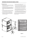
Assemble the gas pipes and ttings provided in the stacking
kit as shown in the Figure 3 on page 7. Use a pipe thread
compound that is intended for use on propane gas piping.
Be sure to check for leaks before nalizing the installation. Use
appropriate solutions or detection devices.
Installations in which a exible gas connection hose is
used, require the supplied strain relief to be installed at the
lower left rear corner of the base. Install the strain relief in
accordance with applicable codes. The strain relief must limit
the movement of the oven to prevent unnecessary stress on
the exible connector.


