Part # MPSM07 (03/24/08) Page 15
Turn on the main gas valve.
Remove the lower front trim cover. Drop the control panel
and leak test all ttings and connections upstream from the
service valve located on the redundant combination gas
valve. Should any gas leaks be detected turn OFF the main
gas valve, correct the problem and begin the test again.
Remove the blanking plug from the manifold test spigot and
connect a pressure test gauge.
Open the manual gas valve located behind the redundant
combination gas valve.
Activate the control panel and set the oven to the desired
temperature. The burner will now ignite.
During installation there will be air in the gas line. This air will
have to bleed o before ignition can occur. Wait ve minutes
after each attempt to bleed the air from the lines.
Turn on all appliances supplied by the same gas line and
verify that the manifold pressure is 4.5” WC for natural gas or
10” WC for propane gas.
GAS MODEL TESTING & LIGHTING INSTRUCTIONS
After the correct pressure has been veried, turn o the oven
and remove the pressure gauge from the manifold pressure
test spigot. Re-install the blanking plug.
Check all ttings again. Correct any leaks and begin the test
again.
Replace all control panels, service panels and covers before
operation.
All electronic ignition systems are supplied with a redundant
gas valve. Therefore, the oven is not supplied with an external
pressure regulator.
To Conserve Energy:
Do not waste energy by leaving the controls at high
temperature settings during idle periods. Lower settings will
keep the oven warm and ready for the next use period.
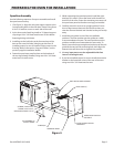
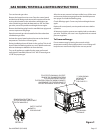
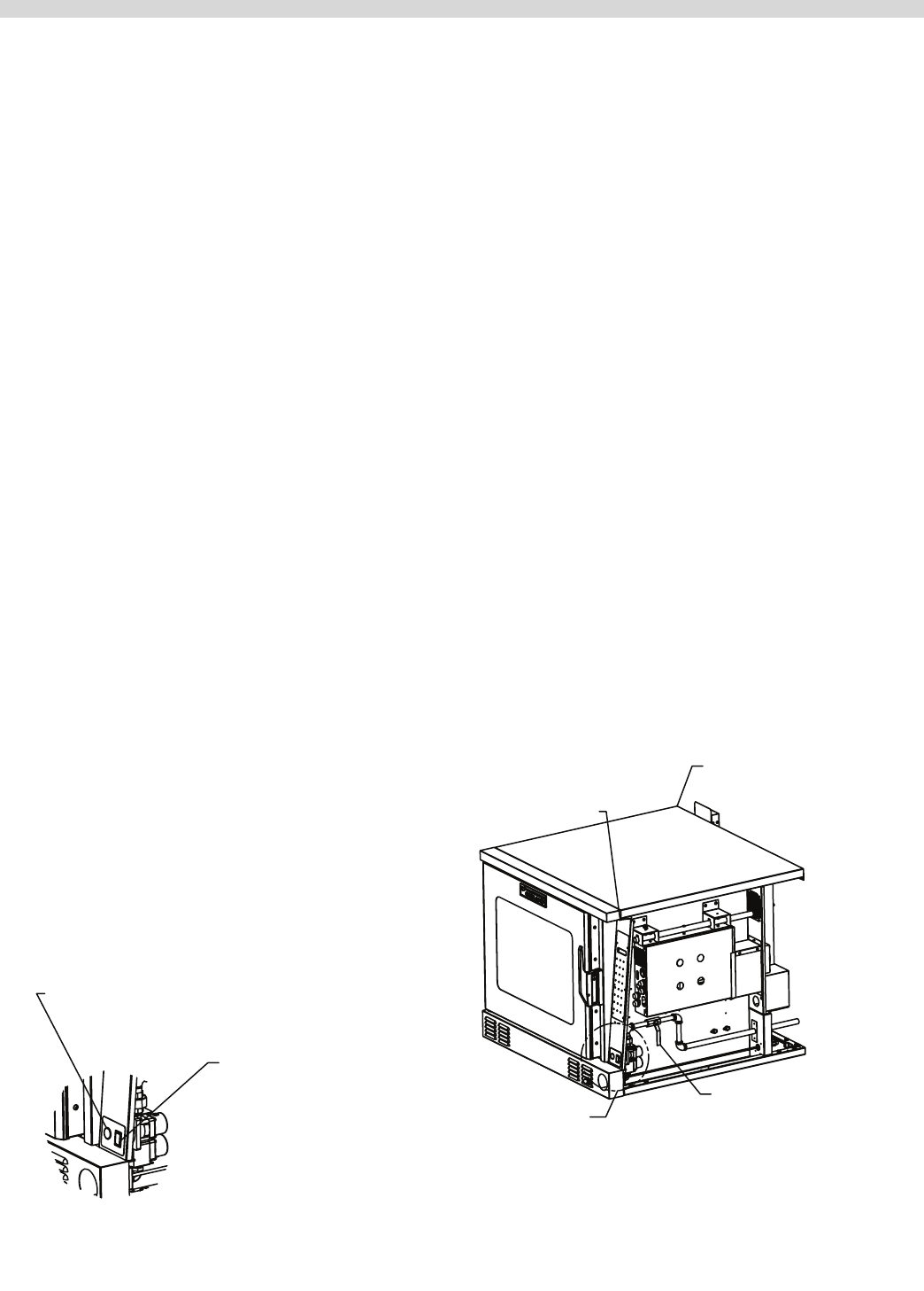
Figure 7.
A
TO ACCESS THE MANUAL SHUTOFF,
REMOVE THE THUMBSCREW FROM
THE CONTROL PANEL, UNPLUG
T
HE CONTROL FROM THE WIRING HARNESS,
AND REMOVE THE CONTROL PANEL TO
EXPOSE THE MANUAL SHUTOFF VALVE.
*** VIEW SHOWN
WITHOUT THE
BODY SIDE
FOR CLARITY***
3/4” MANUAL
GAS VALVE
A
REMOVE PLUG BUTTON TO
ACCESS PRESSURE ADJUSTMENT
FOR THE MANIFOLD
SAFETY SHUTOFF
SWITCH
FOR GAS VALVE
DETAIL A


