Part # MPSM07 (03/24/08)Page 58
8. Test door switch activation / operation as indicated in the
diagnostic checks.
9. If the door switch assembly requires adjustment, position
the door to the full close position. Loosen the assembly
mount screws just enough to set the switch stricker arm
rollers at a position where there is no pressure on the rollers
at either cam surface.
10. At that point, tighten the switch assembly bracket screws.
11. Run the door position diagnostic check again.
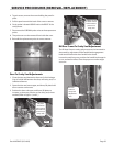
Oven Temperature Probe Service/Removal
The probe is located on the interior RIGHT rear side of the
oven cavity.
1. To rst gain access to the temperature probe, remove the
oven racks, rack support guides and bale plate. Remove
the 2 screws holding the probe in place. DO NOT REMOVE
THE PROBE at this point.
2. Remove the 2 screws holding the probe in place.
3. DO NOT REMOVE THE PROBE at this point.
Note: The wires for the probe are located behind the RIGHT
side panel.
SERVICE PROCEDURES (REMOVAL/REPLACEMENT)
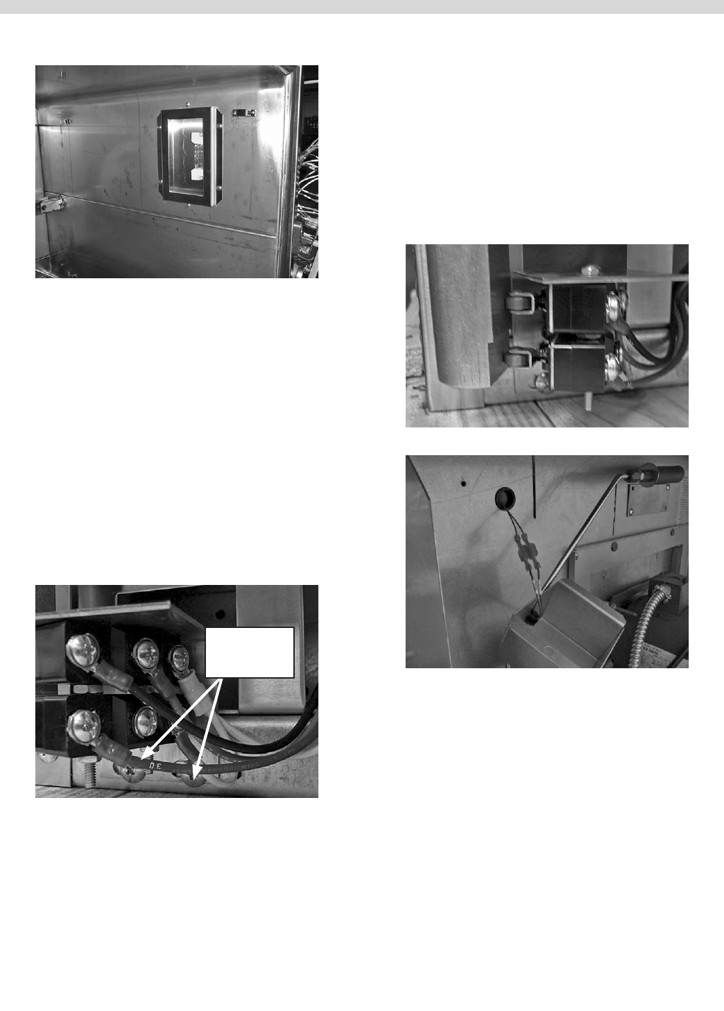
6. Use a clean dry cloth to hold the new light, DO NOT
TOUCH NEW LIGHT WITH YOUR FINGERS.
7. Install the replacement light.
8. To reassemble, reverse above instructions. Ensure that the
cavity light wires on the RIGHT side of the oven are re-
connected
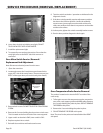
Door Micro Switch Service / Removal /
Replacement And Adjustment
Note: Disconnect electrical power from the oven.
1 Open the oven door.
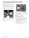
2. Locate and remove the 2 machine screws located in the
upper LEFT side of the cavity frame. (These screws are just
RIGHT of the upper door post on the cavity door frame.)
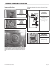
Door Switch
adjustment
screws
3 Remove both screws. DO NOT TOUCH THE COUNTERSINK
SCREW.
4. Remove the 2 screws holding the door micro switch cover.
This is located on the front LH side of the oven top panel.
5. Upper switch on bracket is SW2, lower switch is SW1.
6 Replace required micro switch.
7. Reinstall door switches and bracket and screws.


