


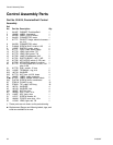
Control Assembly Service
28 310554V
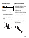
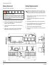
Potentiometer Removal
Remove the potentiometer as follows:
1. Shut off system power at the main circuit breaker.
2. At the control assembly, move the MAIN power
switch to the OFF position.
3. Unlock and open the hinged cover of the control
assembly.
4. Pull lead wires to remove from potentiometer.
5. Loosen setscrew (not shown) in the vernier dial
knob and remove dial assembly from the potentiom-
eter shaft.
6. Remove the hex nut and lockwasher from potenti-
ometer shaft, and remove the potentiometer.
Potentiometer Replacement
Replace the potentiometer as follows:
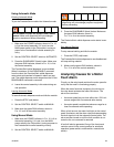
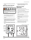
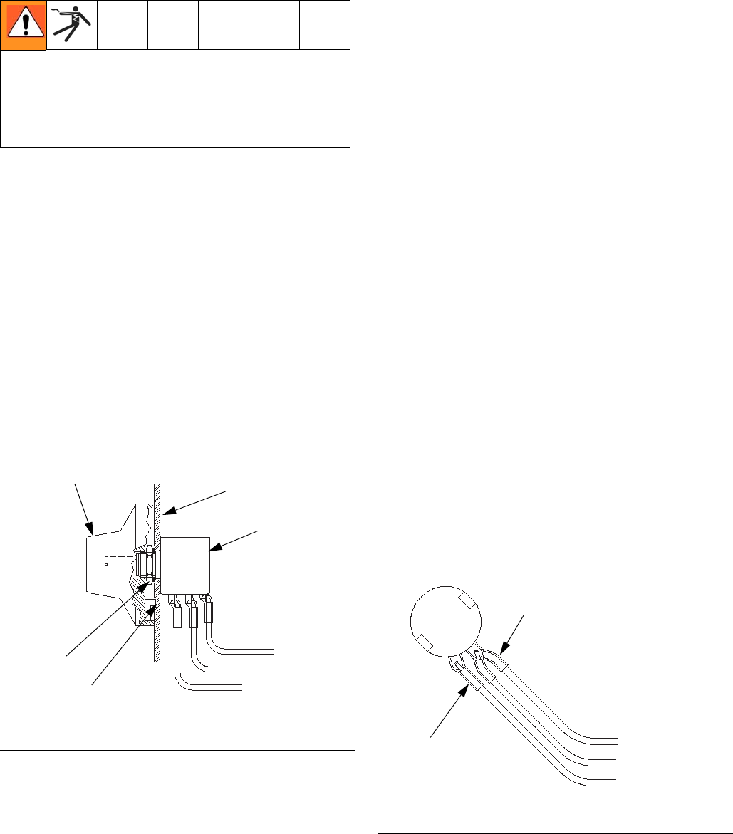
1. Insert the potentiometer through its hole from the
back of the enclosure cover and rotate it so that ter-
minals 1 and 3 are oriented at approximately 4:30
when viewed from the back. Refer to F
IG. 16.
Assemble the lockwasher and nut onto the shaft and
secure the potentiometer to the cover.
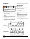
2. At the front of the cover, turn the potentiometer shaft
counter–clockwise to its stop.
3. Pre–set the vernier dial to 0.00 and place it over the
potentiometer shaft, with its key tab inserted into the
blind hole in the cover front surface. Tighten the dial
setscrew (not shown) against the shaft.
4. Verify that the potentiometer is turned fully counter-
clockwise when the vernier dial indicates 0.00.
Loosen the setscrew and reposition the shaft and
dial if necessary, then retighten the setscrew.
5. Connect wire leads to potentiometer.
6. Close and lock the cover on the control assembly.
7. Apply system power at the main circuit breaker.
8. Move the MAIN power switch to the ON position,
applying power to the control assembly.
9. In the MANUAL control mode, verify that the potenti-
ometer operates correctly.
10. Return the orbital dispenser and control assembly to
normal operating condition.
ELECTROCUTION HAZARD
Installing and servicing this equipment requires access
to parts which could cause an electric shock or other
serious injury. Have only qualified electricians access
the control assembly.
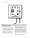
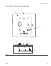
F
IG. 15
321
Cover
Potentiometer
Nut
Locating
Tab
Vernier dial
2172
2132
2181
8040A
FIG. 16
Terminals 1 and 3
Terminal 2
2181
2132
2172
8034B