


Pump Assembly
312393G 34 of 50
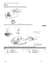
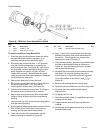
To install a new Air Cylinder Kit:
1. Follow the Pressure Relief Procedure and turn off the
machine.
2. Disconnect the airline, remove the PR70 Shroud, and
remove the machine power entry assembly (item 3 or
Figure 40) from the machine by removing the 2
attachment screws (4 of Figure 40).
3. Remove the 2 air valves (items 7 & 8) from the cylinder
end block (18) by removing the 3 attachment screws (2).
4. Disconnect the air cylinder piston rod (20) from the
machine drive block assembly (item 5 of Figure 39) by
removing all hex nuts (item 3 of Figure 39) from the piston
rod (additional nuts may be installed if the machine has a
Hydracheck option). An open-end wrench will be
required to prevent the rod from turning when the nuts are
removed.
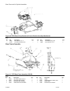
5. Disconnect the air cylinder from the machine frame base
assembly (item 7 of Figure 39) by removing the 4 screws
(item 8 of figure 39), which attach the cylinder rod end
block (17) to the frame. Access the screw through the 4
holes in the blind end block (18) using a long allen
wrench.
6. Remove the air cylinder by pulling on the cylinder from
the back of the machine.
7. With the cylinder partially removed, disconnect the
airlines at the air cylinder elbow fittings (12).
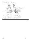
8. On a bench, disassemble the air cylinder by removing the
4 long screws (4), which connect the 2 cylinder blocks.
9. Inspect the cylinder tube (16) and piston (19) to verify no
scratches exists. Replace if necessary.
10. Using a clean dry cloth, remove any existing grease from
the inside of the tube (16), the outside of the piston (19)
and the cylinder rod (20).
11. Remove the 2 cylinder block o-rings (item 2 of Figure 40)
from the blocks and replace. Remove the piston o-ring
and replace (item 1 of Figure 40).
12. Remove the cylinder rod from the rod end block, then
remove the rod o-ring (item 3 of Figure 40) from the rod
end block and replace.
13. Liberally apply Graco high temperature lubricant Grease
(Graco P/N 115982) to the inside of the tube (16), the
outside of the piston (19), all the o-rings and the cylinder
rod (20).
14. Re-assemble the air cylinder. Attach the 2 drive blocks
by reinstalling the 4 long screws (4) finger tight. Then
torque the screws as specified in note
of Figure 43 in
a crisscross pattern.
NOTICE
In the previous step, air cylinder damage may result if
screws are not installed in a crisscross pattern.
15. Air Cylinder damage may result if bolts are not installed in
a crisscross pattern.
16. Reinsert the air cylinder into the back of the machine by
inserting the cylinder rod through the hole in the base
frame and in the drive block.
17. Before the cylinder is completely in place, re-connect the
airlines to the cylinder block elbows fittings (12). Verify
the correct airlines are connected (see Figure 43).
18. Reattach the cylinder to the base frame by reinstalling the
4 screws (item 8 of Figure 39).
19. Reattach the cylinder to the drive block by reinstalling the
hex nut (item 3 of Figure 39) to the cylinder rod. Torque
the nut as specified in note
of Figure 39.
20. Reattach the valves to the blind end block by reattaching
the 3 screws (2).
21. Reattach the power entry assembly by reinstalling the 2
attachment screws (item 4 of Figure 40).
22. Reconnect input air into the machine. Operate the
machine accordingly
, and verify no air leaks are found.
Recalibrate the machine.
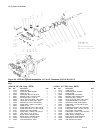
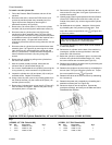
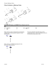
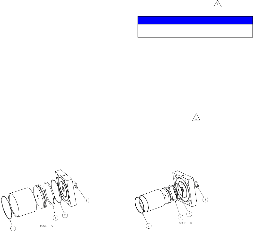
Figure 44: PR70 Air Cylinder Rebuild Kits, 4.5” and 3.0” Diameter Versions (LC0092 & LC0091).
Key:
(LC0092, 4.5” DIA. Rebuild Kit) (LC0091, 3.0” DIA. Rebuild Kit)
Ref P/N Description QTY Ref P/N Description QTY
1 104131 ORING, VIT, CDG 1 1 120875 ORING, VIT, CCE 1
2 104271 ORING, VIT, JDG 2 2 120932 ORING, VIT, JDA 2
3 107571 ORING, VIT, BAD 1 3 107571 ORING, VIT, BAD 1