


220 Connecting and Testing the Power Supply
Note 1:
Verify that the AC outlet is supplying 11% AC
and provides good conduit ground. If there is a
problem with the AC voltage, have it corrected.
If there is no conduit ground, provide alternate
ground as explained in Section 120, “Grounding
Requirements”, of this manual.
Note 2: Before proceeding, ensure that the PS-6-I Power
Cord is unplugged. The PS-6-I Power Switch
should be off, and its power indicator lamps should
1.
2.
Remove the 9-pin connectorended cable of the power
supply from the connector of the KSU.
Plug the AC cord of the power supply into an AC
outlet. Set PSU Power switch to on position. The PSU
Power Indicator Lamp should
light.
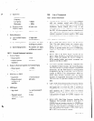
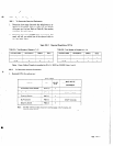
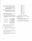
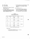
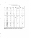
Use a voltmeter,
to the figure below:
Fig. 220-I Front View of g-pin Connector of PS-6-l
3.
Set PSU Power Switch to Off Position
Note:
Verify that step
3
has been completed before pro-
ceeding. Verify that PS-6-I Power Indicator Lamp
I
is off:
4.
Connect the 9-pin connectorended cable of the Power
Supply Unit to the 9-pin connector of the KSU. Ensure
that the looking tabs are engaged.
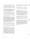
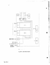
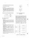
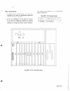
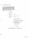
5. Turn the PSU Power Switch on. DC voltage (under
load) can now be read on the TBl terminal block
located on the left side of KSU.
t
1
I
03
I@/
I
e3
I@I
I I
cl3
H
e3
,
I
+41v
+24V
+12v
+5v
+41G
+24G
+12G
+5G
+12G
+5G
7
Fig. 220-2 View of TBI Terminal Block
When measuring DC voltages, note that each voltage has
its own reference ground.
6. The Power Supply Switch must be set in the Offposi-
tion before proceeding with installation.
Note:
Veriyy that Step 6 has been completed before pro-
ceeding. Verify that PS-6-i Power indicator Lamp-
is oft
1
@)
I
Page 200-2