


F--
230
Installation of
KTUs
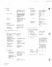
Note: The following KTUs cannot be inserted or removed
with power on:
CPU-S
KSI-S DPH-S
CLK-S
DCI-S
PBS-S
SWM-S
MFI-S
AHR-S
-_. _... .._ .._ _._. - .- .__J
230.1
General Information
1.
The KTUs specified directly above cannot be inserted
or removed -with power on. It is recommended that
power be OFF during installation and during mainte-
nance unless this will seriously inconvenience the user.
This will prevent accidental damage to equipment.
The KTUs used in the Electra-616 system make ex-
tensive use of CMOS technology. Care must be taken
to avoid static discharge when handling these KTUs.
KTUs are provided with a guide slot to prevent mis-
installation. KTU connectors are provided with a guide
key. These guide keys must not be removed.
230.2
Installing Basic MTUs
T
1
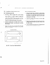
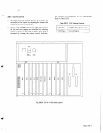
DC1 -S and MFI -S KTUs
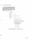
When installing DCI-S and MFI-S KTUs there may
be more KTU circuits installed (since there are 3 per
KTU) then will actually be used. Any non-used circuits
should be programmed as “not installed” when pro-
gramming for CO/PBX line assignment. See Section
300 “Programming”
of this manual for instructions
on programming CO/PBX line assignment. This will
avoid confusion when attempts to access unconnected
CO/PBX lines are made. The DSI-S or MFI-S in the
first designated KTU position (DCI/MFI 1) serve CO/
PBX lines 1 through 3. A DCI-S or MFI-S in the
second designated KTU position (DCI/MFI 2) serve
CO/PBX lines 4 through 6. Refer to figure 230-2 for
KTU positions in the Key Service Unit. See AHR-S
KTU in Section 230 for information’on wiring change
for providing Automatic Hold Release feature when
AHR-S KTU is installed.
2.
KS1 -S KTU
There are two designated KS1 KTU positions within
the Key Service Unit. The KS1 -S in the first position
(KS1 1) serves stations 1 through 8, while a KSI-S in
the second position (KS1 2) serves stations 9 through
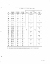
16. Located on each KS!-S KTU are 8 fuses which
are Smm by 20mm and are rated OSA 125V: one
fuse for each keyset. The fuse provides protection on
the data transmission pairs (DT and DR). When a fuse
must be replaced refer to Section 140, “Fuse Replace-
ment” of this manual.
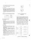
3. SWM-SKTU
An SWM -S KTU must always be installed in SWM 1.
An SWM-S KTU must be installed in SWM2 when
either stations 9
- 16 and/or CO/PBX lines 4 - 6 are
to be connected.
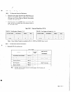
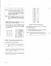
Table 230-I
Installing SWM-S KTUs
SWM -S
SLOT
WHEN
/ SWMl
/
For Stations 1
- 8 and CO/PEX lines 1 - 3.
SWM2
For Stations 9 -
16 and/co CO/PBX lines 4 - 6.
230.3 Installing &mmon KTUs
I.
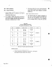
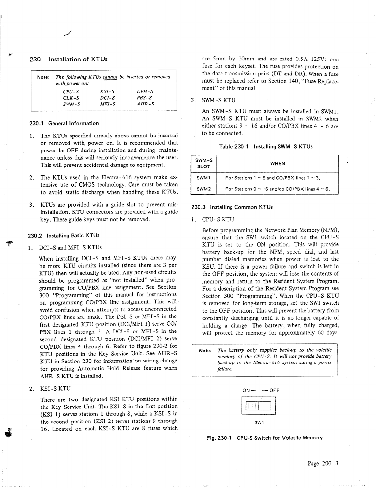
CPU-S STU
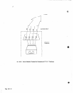
Before programming the Network Plan Memory (NPM),
ensure that the SW1 switch located on the CPU-S
KTU is set to the ON position. This will provide
battery back-up for the NPM, speed dial, and last
number dialed memories when power is lost to the
KSU. If there is a power failure and switch is left in
the OFF position, the system will lose the contents of
memory and return to the Resident System Program.
For a description of the Resident System Program see
Section 300 “Programming”. When the CPU-S KTU
is removed for long-term storage, set the SW1 switch
to the OFF position. This will prevent the battery from
constantly discharging until it is no longer capable of
holding a charge. The battery, when fully charged,
will protect the memory for approximately 60 days.
back-up to the Electra-616 system during a power
I
failure.
ON-
-- OFF
SW1
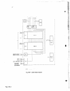
Fig. 230-l
CPU-S Switch for Volatile Memory
Page
290-3