


1-12
a. This test requires a DC millivolt meter set to a scale of 0-1000mv.
b. Locate the thermopile wires coming from the thermostat/High Limit box going to the gas
shut off valve. The wire insulation size decreases near the gas valve connections.
c. Connect the negative (-) test probe to pilot bracket.
d. Connect the positive (+) test probe to to one of the High Limit terminal connections
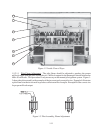
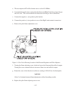
e. Remove the pilot flame adjustment cover.
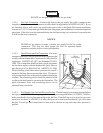
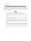
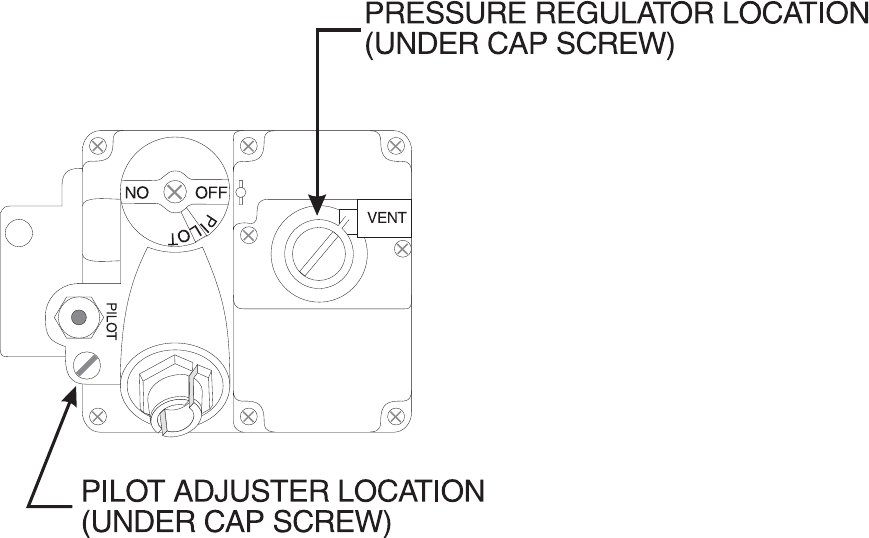
Figure 1-4 Gas Valve Showing Location of the Pressure Regulator and Pilot Adjusters
f. Turning the flame adjusting screw clockwise lowers the flame and the millivolt output.
Turning the screw counterclockwise increases flame size and millivolt output.
g. Rotate the screw in the direction to achieve a reading of 400 ±50 mv for thermopiles.
NOTICE
Allow 3 to 5 minutes between flame adjustments to allow the reading to settle.
h. Replace the pilot flame adjusting screw cover.
IN