


R216LS
8 – 2
6. Reinstall the outer case (cabinet).
7. Reconnect the power supply cord after the outer case is installed.
8. Run the oven and check all functions.
NOTE: Be sure to use an ohmmeter that will supply a forward bias voltage of more than 6.3 volts.
[4] Procedure D: HIGH VOLTAGE CAPACITOR TEST
1. Disconnect the power supply cord, and then remove outer case.
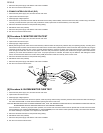
2. Open the door and block it open.
3. Discharge high voltage capacitor.
4. If the capacitor is open, no high voltage will be available to the magnetron. Disconnect input leads and check for short or open between the termi-
nals using an ohmmeter.
Checking with a high ohm scale, if the high voltage capacitor is normal, the meter will indicate continuity for a short time and should indicate an
open circuit once the capacitor is charged. If the above is not the case, check the capacitor with an ohmmeter to see if it is shorted between either
of the terminals and case. If it is shorted, replace the capacitor.
5. Reconnect all leads removed from components during testing.
6. Reinstall the outer case (cabinet).
7. Reconnect the power supply cord after the outer case is installed.
8. Run the oven and check all functions.
[5] Procedure E: TEMPERATURE FUSE (OVEN) TEST
1. Disconnect the power supply cord, and then remove outer case.
2. Open the door and block it open.
3. Discharge high voltage capacitor.
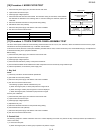
4. A continuity check across the temperature fuse terminals should indicate a closed circuit unless the temperature of the temperature fuse reaches
approximately 302°F(150°C).
An open temperature fuse indicates overheating of the oven, exchange the temperature fuse and check inside of oven cavity and for improper set-
ting of cooking time or operation of control unit. Check for restricted air flow through the vent holes of the oven cavity, especially the cooling fan
and air guide.
5. Reconnect all leads removed from components during testing.
6. Reinstall the outer case (cabinet).
7. Reconnect the power supply cord after the outer case is installed.
8. Run the oven and check all functions.
CAUTION: IF THE TEMPERATURE FUSE INDICATES AN OPEN CIRCUIT AT ROOM TEMPERATURE, REPLACE IT
[6] Procedure F: SECONDARY INTERLOCK SWITCH TEST
1. Disconnect the power supply cord, and then remove outer case.
2. Open the door and block it open.
3. Discharge high voltage capacitor.
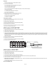
4. Isolate the switch and connect the ohmmeter to the common (COM.) and normally open (NO) terminal of the switch. The meter should indicate an
open circuit with the door open and a closed circuit with the door closed. If improper operation is indicated, replace the secondary interlock switch.
5. Reconnect all leads removed from components during testing.
6. Reinstall the outer case (cabinet).
7. Reconnect the power supply cord after the outer case is installed.
8. Run the oven and check all functions.
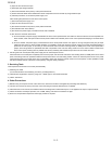
[7] Procedure F: PRIMARY INTERLOCK SYSTEM TEST
1. DOOR SENSING SWITCH
1. Disconnect the power supply cord, and then remove outer case.
2. Open the door and block it open.
3. Discharge high voltage capacitor.
4. Isolate the switch and connect the ohmmeter to the common (COM.) and normally open (NO) terminal of the switch. The meter should indicate an
open circuit with the door open and a closed circuit with the door closed. If improper operation is indicated, replace the door sensing switch.
5. Reconnect all leads removed from components during testing.
6. Reinstall the outer case (cabinet).