


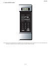

R216LS
8 – 4
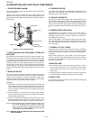
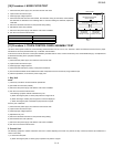
[10] Procedure I: NOISE FILTER TEST
1. Disconnect the power supply cord, and then remove outer case.
2. Open the door and block it open.
3. Discharge high voltage capacitor.
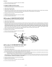
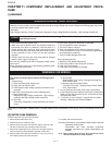
4. Disconnect the lead wires from the terminal the noise filter. Using an ohmmeter, check between
the terminals as described in the following table. If incorrect reading are obtained, replace the
noise filter.
5. Reconnect all leads removed from components during testing.
6. Reinstall the outer case (cabinet).
7. Reconnect the power supply cord after the outer case is installed.
8. Run the oven and check all functions.
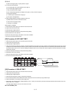
[11] Procedure J: TOUCH CONTROL PANEL ASSEMBLY TEST
The touch control panel consists of circuits including semiconductors such as LSI, ICs, etc. Therefore, unlike conventional microwave ovens, proper
maintenance cannot be performed with only a voltmeter and ohmmeter.
In this service manual, the touch control panel assembly is divided into two units, Control Unit and Key Unit, and troubleshooting by unit replacement
is described according to the symptoms indicated.
Before testing,
1) Disconnect the power supply cord and then remove outer case.
2) Open the door and block it open.
3) Discharge high voltage capacitor.
4) Disconnect the leads to the primary of the power transformer.
5) Ensure that these leads remain isolated from other components and oven chassis by using insulation tape.
6) After that procedure, re-connect the power supply cord.
1. Key Unit
NOTE:
1) Check key unit ribbon connection before replacement.
2) )Re-install the outer case (cabinet).
3) Reconnect the power supply cord after the outer case is installed.
4) Run the oven and check all functions.
The following symptoms indicate a defective key unit.
a) When touching the pads, a certain pad produces no signal at all.
b) When touching a number pad, two figures or more are displayed.
c) When touching the pads, sometimes a pad produces no signal.
If the key unit is defective.
1) Disconnect the power supply cord and then remove outer case.
2) Open the door and block it open.
3) Discharge high voltage capacitor.
4) Replace the key unit.
5) Reconnect all leads removed from components during testing.
6) Re-install the outer case (cabinet).
7) Reconnect the power supply cord after the outer case is installed.
8) Run the oven and check all functions.
2. Control Unit.
The following symptoms indicate a defective control unit. Before replacing the control unit, perform the Key unit test (Procedure K) to determine if
control unit is faulty.
1) In connection with pads.
a) When touching the pads, a certain group of pads do not produce a signal.
MEASURING POINT INDICATION OF OHMMETER
Between N and L Open circuit.
Between terminal N and WHITE Short circuit.
Between terminal L and RED Short circuit.
FUSE 15A
NOISE FILTER
NOISE SUPPRESSION COIL
LINE CROSS CAPACITOR
0.22μF / AC 250V
LINE BYPASS
CAPACITOR
0.0033μF / AC 250V
LINE BYPASS
CAPACITOR
0.0033μF / AC 250V
L
REDWHITE
N