


R216LS
8 – 5
b) When touching the pads, no pads produce a signal.
2) In connection with indicators
a) At a certain digit, all or some segments do not light up.
b) At a certain digit, brightness is low.
c) Only one indicator does not light.
d) The corresponding segments of all digits do not light up; or they continue to light up.
e) Wrong figure appears.
f) A certain group of indicators do not light up.
g) The figure of all digits flicker.
3) Other possible problems caused by defective control unit.
a) Buzzer does not sound or continues to sound.
b) Clock does not operate properly.
c) Cooking is not possible.
When testing is completed,
1) Disconnect the power supply cord and then remove outer case.
2) Open the door and block it open.
3) Discharge high voltage capacitor.
4) Reconnect all leads removed from components during testing.
5) Re-install the outer case (cabinet).
6) Reconnect the power supply cord after the outer case is installed.
7) Run the oven and check all functions.
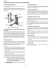
[12] Procedure K: KEY UNIT TEST
1. Disconnect the power supply cord, and then remove outer case.
2. Open the door and block it open.
3. Discharge high voltage capacitor.
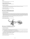
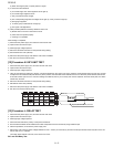
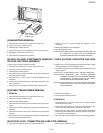
4. Using an ohmmeter and referring to the key unit matrix indicated on the control unit circuit, check the circuit between the pins of the key unit that
correspond to the STOP/CLEAR pad. When the pad is pressed, the ohmmeter should indicate short circuit. When the pad is released, the ohmme-
ter should indicate open circuit. If incorrect readings are obtained, the key unit is faulty and must be replaced. About the other pads, the above
method may be used.
5. Reconnect all leads removed from components during testing.
6. Reinstall the outer case (cabinet).
7. Reconnect the power supply cord after the outer case is installed.
8. Run the oven and check all functions.
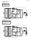
[13] Procedure L: RELAY TEST
1. Disconnect the power supply cord, and then remove outer case.
2. Open the door and block it open.
3. Discharge high voltage capacitor.
4. Disconnect the leads to the primary of the power transformer.
5. Ensure that these leads remain isolated from other components and oven chassis by using insulation tape.
6. After that procedure, re-connect the power supply cord.
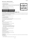
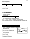
7. Remove the outer case and check voltage between Pin No. 1 of the 3 pin connector (A) and the normal open terminal of the relay RY2 on the con-
trol unit with an A.C. voltmeter.
The meter should indicate 120 volts, if not check oven circuit.
RY1 and RY2 Relay Test
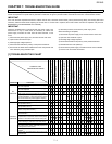
G4 G5 G6G1
G8
G9
G10
G2 G3
G7
REHEAT
4
1
7
2
5
8
0
6
3
TIMER
CLOCK
9
COOK
SOFTEN
WARM
POPCORN
DEFROST
POWER
LEVEL
STOP
CLEAR
START
MINUTE PLUS
Pin NO. G1 Pin NO. G10
Key unit ribbon
cable
Key unit (Membrane Switch) front view