


R216LS
8 – 3
7. Reconnect the power supply cord after the outer case is installed.
8. Run the oven and check all functions.
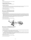
2. PRIMARY INTERLOCK RELAY (RY2)
1. Disconnect the power supply cord, and then remove outer case.
2. Open the door and block it open.
3. Discharge high voltage capacitor.
4. Disconnect two (2) wire leads from the male tab terminals of the Primary Interlock Relay. Check the state of the relay contacts using a ohmmeter.
The relay contacts should be open. If the relay contacts are closed, replace the circuit board entirely or the relay itself.
5. Reconnect all leads removed from components during testing.
6. Reinstall the outer case (cabinet).
7. Reconnect the power supply cord after the outer case is installed.
8. Run the oven and check all functions.
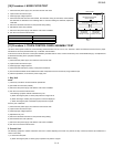
[8] Procedure G: MONITOR SWITCH TEST
1. Disconnect the power supply cord, and then remove outer case.
2. Open the door and block it open.
3. Discharge high voltage capacitor.
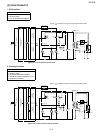
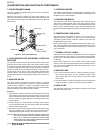
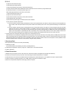
4. Before performing this test, make sure that the secondary interlock switch and the primary interlock relay are operating properly, according to the
above Switch Test Procedure. Disconnect the wire lead from the monitor switch (COM) terminal. Check the monitor switch operation by using the
ohmmeter as follows. When the door is open, the meter should indicate a closed circuit. When the monitor switch actuator is pushed by a screw
driver through the lower latch hole on the front plate of the oven cavity with the door opened (in this condition the plunger of the monitor switch is
pushed in), the meter should indicate an open circuit. If improper operation is indicated, the switch may be defective. After testing the monitor
switch, reconnect the wire lead to the monitor switch (COM) terminal and check the continuity of the monitor circuit.
5. Reconnect all leads removed from components during testing.
6. Reinstall the outer case (cabinet).
7. Reconnect the power supply cord after the outer case is installed.
8. Run the oven and check all functions.
[9] Procedure H: BLOWN MINITOR FUSE TEST
1. Disconnect the power supply cord, and then remove outer case.
2. Open the door and block it open.
3. Discharge high voltage capacitor.
4. If the monitor fuse is blown when the door is opened, check the primary interlock relay, secondary interlock switch and monitor switch according to
the "TEST PROCEDURE" for those switches before replacing the blown monitor fuse.
CAUTION: BEFORE REPLACING A BLOWN MONITOR FUSE, TEST THE PRIMARY INTERLOCK RELAY, SECONDARY INTERLOCK SWITCH,
DOOR SENSING SWITCH AND MONITOR SWITCH FOR PROPER OPERATION.
If the monitor fuse is blown by improper switch operation, the monitor fuse and monitor switch must be replaced with "monitor fuse and monitor
switch assembly" part number FFS-BA026WRKZ or FFS-BA038WRKZ, even if the monitor switch operates normally. The monitor fuse and mon-
itor switch assembly is comprised of a 15 ampere fuse and switch.
5. Reconnect all leads removed from components during testing.
6. Reinstall the outer case (cabinet).
7. Reconnect the power supply cord after the outer case is installed.
8. Run the oven and check all functions.
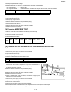
SCREW
DRIVER
BLK
GRY
MO NI TOR
SWITCH
O HMME T ER