


R216LS
11 – 6
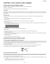
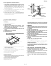
2. After adjustment, check the following.
1. In and out play of door remains less than 0.5mm when in the
latched position. First check upper position of latch hook, pushing
and pulling upper portion of door toward the oven face. Then check
lower portion of the latch hook, pushing and pulling lower portion of
the door toward the oven face. Both results (play in the door)
should be less than 0.5mm.
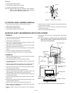
2. The door sensing switch and secondary interlock switch interrupt
the circuit before the door can be opened.
3. Monitor switch contacts close when door is opened.
4. Re-install outer case and check for microwave leakage around
door with an approved microwave survey meter. (Refer to Micro-
wave Measurement Procedure.)
Figure C-5. Latch Switch Adjustments
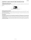
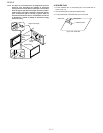
[14] DOOR REPLACEMENT
1. REMOVAL
1. Disconnect the power supply cord.
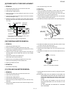
2. Open the door slightly.
3. Insert a putty knife (thickness of about 0.5mm) into the gap
between the choke cover and corner portion of door panel as
shown in Figure C-6 to free engaging parts.
4. Pry the choke cover by inserting a putty knife in order shown in fig-
ure C-6.
5. Release choke cover from door panel.
6. Now choke cover is free.
NOTE: When carrying out any repair to the door, do not bend or
warp the slit choke (tabs on the door panel assembly) to
prevent microwave leakage.
Figure C-6. Door Disassembly
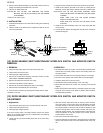
7. Release two (2) pins of door panel from two (2) holes of upper and
lower oven hinges by lifting up.
8. Now, door panel is free from oven cavity.
9. Release door panel from ten (10) tabs of door frame and remove
door frame by sliding the door panel downward.
10.Now, door panel with sealer film is free.
11.Tear sealer film from door panel.
12.Now, door panel is free.
13.Slide latch head upward and remove it from door frame with releas-
ing latch spring from door frame and latch head.
14.Now, latch head and latch spring are free.
15.Remove door screen from door frame.
16.Now, door screen is free.
17.Unfolded each six (6) tab of the door decoration upper and lower by
using a pair of needle-nose pliers. And remove the door decoration
upper and lower from the door frame. Now, the door frame is loose.
2. REINSTALL
1. Insert each six (6) tab of the door decoration upper and lower into
each slit of the door frame and bend the tabs by using a pair of nee-
dle-nose pliers.
2. Re-install door screen to door frame.
3. Re-install latch spring to the head. Re-install latch spring to the
door frame. Re-install latch head to the door frame.
4. Re-install door panel to door frame by fitting ten (10) tabs of door
frame to ten (10) holes of door panel.
5. Put sealer film on door panel. Refer to "Sealer Film" and figure C-8,
on how to handle the new film.
6. Catch two (2) pins of door panel on two (2) hole of upper and lower
oven hinges.
7. Re-install choke cover to door panel by pushing.
NOTE: After any service to the door;
1) Make sure that door sensing switch, secondary interlock
switch and monitor switch are operating properly. (Refer to
chapter "Test Procedures".).
2) An approved microwave survey meter should be used to
assure compliance with proper microwave radiation emission
limitation standards.
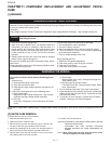
3. After any service, make sure of the following :
1. Door latch heads smoothly catch latch hook through latch holes
and that latch head goes through center of latch hole.
2. Deviation of door alignment from horizontal line of cavity face plate
is to be less than 1.0mm.
3. Door is positioned with its face pressed toward cavity face plate.
4. Check for microwave leakage around door with an approved micro-
wave survey meter. (Refer to Microwave Measurement Proce-
dure.)
Latch
Heads
Door
Switch Lever
Latch Hook
Monitor Switch
Door Sensing
Switch
Secondary
Interlock Switch
10
5
4
8
7
9
11
3
2
1
Chok e C over
Door Frame
P utty Knife
6