


R216LS
11 – 2
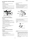
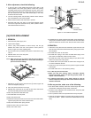
[3] MAGNETRON REMOVAL
1. Disconnect the power supply cord and remove outer case.
2. Open the oven door and block it open.
3. Discharge high voltage capacitor.
4. Remove the two (2) screws holding the air duct to the oven cavity.
5. Release the air duct from the oven cavity.
6. Disconnect the wire leads from magnetron.
7. Remove the four (4) screws holding the magnetron to the
waveguide.
8. Remove the magnetron from waveguide.
9. Now, the magnetron is free.
CAUTION: WHEN REPLACING THE MAGNETRON, BE SURE THE
R.F. GASKET IS IN PLACE AND THE MAGNETRON
MOUNTING SCREWS ARE TIGHTENED SECURELY.
[4] HIGH VOLTAGE COMPONENTS REMOVAL? (?HIGH VOLTAGE CAPACITOR AND HIGH
VOLTAGE RECTIFIER ASSEMBLY)
To remove the components, proceed as follows.
1. Disconnect the power supply cord and remove outer case.
2. Open the oven door and block it open.
3. Discharge high voltage capacitor.
4. Disconnect the high voltage wire (white) of the power transformer
from high voltage capacitor.
5. Disconnect the H.V. wire of the H.V. rectifier assembly from the
magnetron.
6. Disconnect the filament lead (red) of the power transformer from
the H.V. capacitor.
7. Remove one (1) screw holding capacitor holder to bottom plate.
8. Remove one (1) screw holding ground side terminal of high voltage
rectifier assembly, and remove capacitor holder.
9. Disconnect the terminal of high voltage rectifier assembly from high
voltage capacitor.
10.Now the H.V. rectifier assembly and H.V. capacitor should be free.
CAUTION: WHEN REPLACING HIGH VOLTAGE RECTIFIER
ASSEMBLY, ENSURE THAT THE CATHODE (GROUND)
CONNECTION IS SECURELY FIXED TO THE CAPACI-
TOR HOLDER WITH A GROUNDING SCREW.
CAUTION: DO NOT REPLACE ONLY HIGH VOLTAGE RECTIFIER.
WHEN REPLACING IT, REPLACE HIGH VOLTAGE REC-
TIFIER ASSEMBLY.
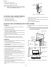
[5] POWER TRANSFORMER REMOVAL
1. REMOVAL
1. Disconnect the power supply cord and remove outer case.
2. Open the oven door and block it open.
3. Discharge high voltage capacitor.
4. Disconnect the wire leads (main wire harness) from power trans-
former.
5. Disconnect the filament lead (red) of the power transformer from
magnetron.
6. Disconnect the leads of the power transformer from high voltage
capacitor.
7. Remove the four (4) screws holding the transformer to bottom plate
from the upper side and bottom side.
8. Remove the transformer.
9. Now the power transformer is free.
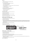
2. REINSTALL
1. Rest transformer on the bottom plate with its primary terminals
toward the oven face plate.
2. Secure transformer with four (4) screws to the bottom plate ( two
screws from upper side and two screws from bottom side).
3. Re-connect wire leads (primary and high voltage) and filament
leads to the power transformer, magnetron and high voltage capac-
itor, referring to "Pictorial Diagram".
4. Re-install outer case and check that the oven is operating properly.
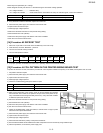
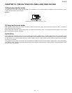
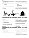
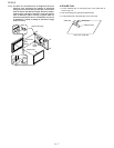
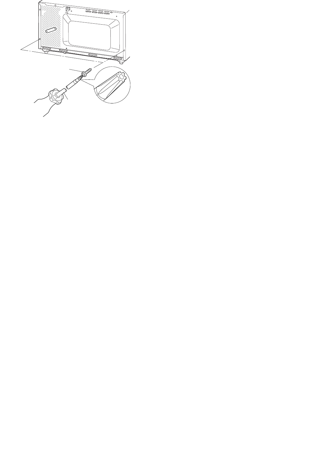
[6] POSITIVE LOCK CONNECTOR (NO-CASE TYPE) REMOVAL
1. Disconnect the power supply cord, and remove outer case. 2. Open the door and block it open.
Special screw
Screw Driver
(Type: TORX T20 H or
GTXH20-100)