


R216LS
9 – 1
R216LS
Service Manual
CHAPTER 9. TOUCH CONTROL PANEL ASSEMBLY
[1] OUTLINE OF TOUCH CONTROL PANEL
The touch control section consists of the following units as shown in the touch control panel circuit.
(1) Key Unit (2) Control Unit
The principal functions of these units and their related signals are explained below.
1. Key Unit
The key unit is composed of a matrix, signals generated in the LSI are sent to the key unit through P24, P25, P26, P31, P32 and P33. When a key
pad is touched, a signal is completed through the key unit and passed back to the LSI through P50, P51, P52 and P53 to perform the function that
was requested.
2. Control Unit
Control unit consists of LSI, reset circuit, indicator circuit, power source circuit, relay circuit, buzzer circuit and synchronizing signal circuit.
1) Reset Circuit
This circuit generates a signal which resets the LSI to the initial state when power is supplied.
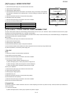
2) Indicator Circuit
This circuit consists of 4-digits, 12-segments and 3-common electrodes using a Liquid Crystal Display.
3) Power Source Circuit
This circuit generates voltage necessary in the control unit from the AC line voltage. In addition, the synchronizing signal is available in order to
compose a basic standard time in the clock circuit.
4) Relay Circuit
To drive the magnetron, fan motor, turntable motor and light the oven lamp.
5) Buzzer Circuit
The buzzer is responsive to signals from the LSI to emit audible sounds (key touch sound and completion sound).
6) Synchronizing Signal Circuit
The power source synchronizing signal is available in order to compose a basic standard time in the clock circuit. It accompanies a very small error
because it works on commercial frequency.
7) Door Sensing Switch
A switch to “tell” the LSI if the door is open or closed.
[2] SERVICING FOR TOUCH CONTROL PANEL
1. Precautions for Handling Electronic Components
This unit uses CMOS LSI in the integral part of the circuits. When handling these parts, the following precautions should be strictly followed. CMOS
LSI have extremely high impedance at its input and output terminals. For this reason, it is easily influenced by the surrounding high voltage power
source, static electricity charge in clothes, etc., and sometimes it is not fully protected by the built-in protection circuit.
In order to protect CMOS LSI.
1) When storing and transporting, thoroughly wrap them in aluminium foil. Also wrap PW boards containing them in aluminium foil.
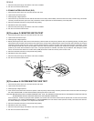
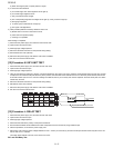
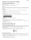
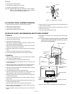
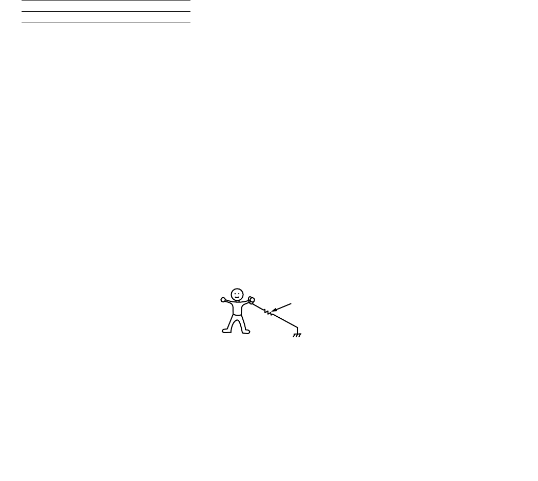
2) When soldering, ground the technician as shown in the figure and use grounded soldering iron and work table.
2. Servicing of Touch Control Panel
We describe the procedures to permit servicing of the touch control panel of the microwave oven and the precautions you must take when doing so.
To perform the servicing, power to the touch control panel is available either from the power line of the oven itself or from an external power source.
1. Servicing the touch control panel with power supply of the oven :
CAUTION: THE HIGH VOLTAGE TRANSFORMER OF THE MICROWAVE OVEN IS STILL LIVE DURING SERVICING AND PRESENTS A HAZ-
ARD .
Therefore, before checking the performance of the touch control panel,
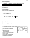
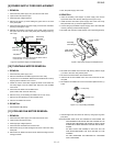
1) Disconnect the power supply cord and then remove outer case.
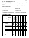
Symbol Voltage Application
VSS -5V LSI(IC1)
approx. 1M ohm