


R216LS
8 – 6
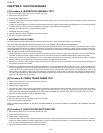
These relays are operated by D.C. voltage
Check voltage at the relay coil with a D.C. voltmeter during the microwave cooking operation.
DC. voltage indicated ................. Defective relay.
DC. voltage not indicated ........... Check diode which is connected to the relay coil. If diode is good, control unit is defective.
8. If any abnormal condition is defected, replace the control unit.
9. Disconnect the power supply cord and then remove outer case.
10.Open the door and block it open.
11.Discharge high voltage capacitor.
12.Reconnect all leads removed from components during testing.
13.Re-install the outer case (cabinet).
14.Reconnect the power supply cord after the outer case is installed.
15.Run the oven and check all functions.
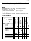
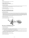
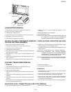
[14] Procedure M: DEFROST TEST
1. Place one cup of water in the center of the turntable tray in the oven cavity.
2. Close the door, touch the “DEFROST “ pad once.
3. The oven is in Defrost cooking condition.
4. The oven will operate as follows.
5. If improper operation is indicated, the control unit is probably defective and should be checked.
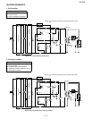
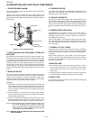
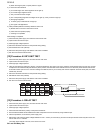
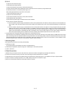
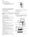
[15] Procedure N: FOIL PATTERN ON THE PRINTED WIRING BOARD TEST
To protect the electronic circuits, this model is provided with a fine foil pattern added to the primary on the PWB, this foil pattern acts as a fuse.
1. Foil pattern check and repairs.
1) Disconnect the power supply cord and then remove outer case.
2) Open the door and block it open.
3) Discharge high voltage capacitor.
4) Follow the troubleshooting guide given below for repair.
5) Make a visual inspection of the varistor. Check for burned damage and examine
the transformer with a tester for the presence of layer short-circuit (check the pri-
mary coil resistance which is approximately 915Ω±10%). If any abnormal condition
is detected, replace the control unit.
6) Reconnect all leads removed from components during testing.
7) Re-install the outer case (cabinet).
8) Reconnect the power supply cord after the outer case is installed.
9) Run the oven and check all functions.
2. Follow the troubleshooting guide given below, if indicator does not light up after
above check and repairs are finished.
1) Disconnect the power supply cord and then remove outer case.
2) Open the door and block it open.
3) Discharge high voltage capacitor.
4) Disconnect the leads to the primary of the power transformer.
5) Ensure that these leads remain isolated from other components and oven chassis by using insulation tape.
6) After that procedure, re-connect the power supply cord.
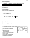
RELAY SYMBOL OPERATIONAL VOLTAGE CONNECTED COMPONENTS
RY1 Approx. 12.5V D.C. Oven lamp / Turntable motor / Cooling fan motor
RY2 Approx. 11.2V D.C. Power transformer
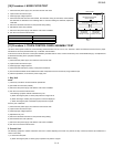
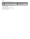
MENU 1ST STAGE 2ND STAGE 3RD STAGE 4TH STAGE
Steaks/
Chops
LEVEL TIME LEVEL TIME LEVEL TIME LEVEL TIME
0.5lb 70% 1min 2sec. 0% 50sec. 50% 37sec. 30% 40sec.
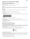
STEPS OCCURRENCE CAUSE OR CORRECTION
1 Only pattern at “a” is broken. *Insert jumper wire J1 and solder.
2 Pattern at “a” and “b” are broken. *Replace control unit.
T1
a
b
c
d
(J1)
VRS1
RY2
RY1
CN-A
1
3