


R216LS
9 – 2
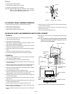
2) Open the door and block it open.
3) Discharge high voltage capacitor.
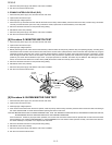
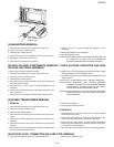
4) Disconnect the leads to the primary of the power transformer.
5) Ensure that these leads remain isolated from other components and oven chassis by using insulation tape.
6) After that procedure, re-connect the power supply cord.
After checking the performance of the touch control panel,
1) Disconnect the power supply cord.
2) Open the door and block it open.
3) Re-connect the leads to the primary of the power transformer.
4) Re-install the outer case (cabinet).
5) Re-connect the power supply cord after the outer case is installed.
6) Run the oven and check all functions.
a) On some models, the power supply cord between the touch control panel and the oven itself is so short that the two can't be separated. For
those models, check and repair all the controls (sensor-related ones included) of the touch control panel while keeping it connected to the
oven.
b) On some models, the power supply cord between the touch control panel and the oven proper is so long enough that they may be sepa-
rated from each other. For those models, therefore, it is possible to check and repair the controls of the touch control panel while keeping it
apart from the oven proper; in this case you must short both ends of the door sensing switch (on PWB) of the touch control panel with a
jumper, which brings about an operational state that is equivalent to the oven door being closed. As for the sensor-related controls of the
touch control panel, checking them is possible if the dummy resistor(s) with resistance equal to that of the controls are used.
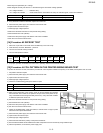
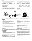
2. Servicing the touch control panel with power supply from an external power source:
Disconnect the touch control panel completely from the oven proper, and short both ends of the door sensing switch (on PWB) of the touch control
panel, which brings about an operational state that is equivalent to the oven door being closed. Connect an external power source to the power
input terminal of the touch control panel, then it is possible to check and repair the controls of the touch control panel; it is also possible to check
the sensor-related controls of the touch control panel by using the dummy resistor(s).
3. Servicing Tools
Tools required to service the touch control panel assembly.
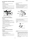
1) Soldering iron: 60W
(It is recommended to use a soldering iron with a grounding terminal.)
2) Oscilloscope: Single beam, frequency range: DC - 10MHz type or more advanced model.
3) Others: Hand tools
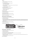
4. Other Precautions
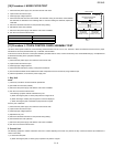
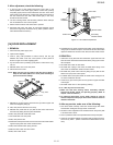
1) Before turning on the power source of the control unit, remove the aluminium foil applied for preventing static electricity.
2) Connect the connector of the key unit to the control unit being sure that the lead wires are not twisted.
3) After aluminium foil is removed, be careful that abnormal voltage due to static electricity etc. is not applied to the input or output terminals.
4) Attach connectors, electrolytic capacitors, etc. to PWB, making sure that all connections are tight.
5) Be sure to use specified components where high precision is required.