


R216LS
11 – 4
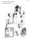
[9] POWER SUPPLY CORD REPLACEMENT
1. REMOVAL
1. Disconnect the power supply cord, and remove outer case.
2. Open the door and block it open.
3. Discharge high voltage capacitor.
4. Remove the single (1) screw holding the green wire to the oven
cavity back plate.
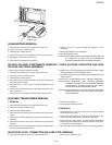
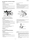
5. Disconnect the leads of the power supply cord from the noise filter,
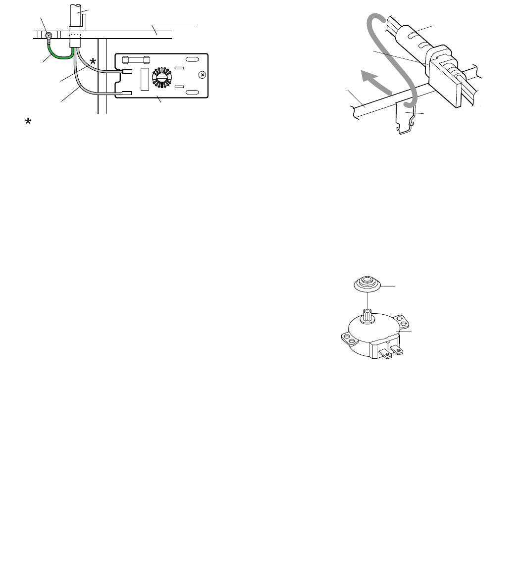
referring to the Figure C-3(a).
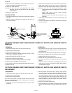
6. Release the moulding cord stopper of the power supply cord from
the square hole of the oven cavity back plate, referring to the Fig-
ure C-3(b).
7. Now, the power supply cord is free.
2. REINSTALL
1. Insert the moulding cord stopper of power supply cord into the
square hole of the rear cabinet, referring to the Figure C-3 (b).
2. Install the earth wire lead of power supply cord to the oven cavity
back plate with one (1) screw and tight the screw.
3. Connect the gray wire leads of power supply cord to the noise filter
correctly, referring to the Pictorial Diagram.
4. Re-install outer case and check that the oven is operating properly.
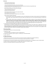
Figure C-3(a) Power Supply Cord Replacement Figure C-3(b) Power Supply Cord Replacement
[10] TURNTABLE MOTOR REMOVAL
1. REMOVAL
1. Disconnect the power supply cord.
2. Remove turntable and turntable support from oven cavity.
3. Lay the oven on it's backside. Remove the turntable motor cover by
snipping off the material in four corners.
4. Where the corners have been snipped off bend corner areas flat.
No sharp edges must be evident after removal of the turntable
motor cover.
5. Disconnect wire leads from turntable motor.
(See "Positive lock connector removal")
6. Remove one (1) screw holding turntable motor to oven cavity.
7. Remove the TTM packing from the turntable motor.
8. Now, the turntable motor is free.
2. REINSTALL
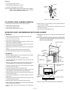
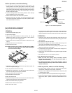
1. Re-install the TTM packing.
2. Re-install the turntable motor with the TTM packing with the single
(1) screw to the oven cavity bottom plate.
3. Re-connect the wire leads to the turntable motor.
4. Insert the tab of the turntable motor cover into the hole of the bot-
tom plate.
5. Re-install the turntable motor cover to the bottom plate with one (1)
screw.
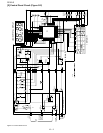
Figure C-4. TTM packing Installation
[11] COOLING FAN MOTOR REMOVAL
1. REMOVAL
1. Disconnect the power supply cord and remove outer case.
2. Open the door and block it open.
3. Discharge high voltage capacitor.
4. Disconnect the wire leads from the fan motor.
5. Remove the two (2) screws holding the fan motor to the oven cavity
back plate.
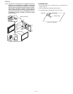
6. Remove the fan blade from the fan motor shaft according to the fol-
lowing procedure.
7. Hold the edge of the rotor of the fan motor by using a pair of groove
joint pliers.
CAUTION: MAKE SURE THAT ANY PIECES DO NOT ENTER THE
GAP BETWEEN THE ROTOR AND THE STATOR OF THE
FAN MOTOR. BECAUSE THE ROTOR IS EASY TO BE
SHAVEN BY PLIERS AND METAL PIECES MAY BE PRO-
DUCED.
DO NOT TOUCH THE PLIERS TO THE COIL OF THE
FAN MOTOR BECAUSE THE COIL MAY BE CUT OR
INJURED.
DO NOT DISFIGURE THE BRACKET BY TOUCHING
WITH THE PLIERS.
L
N
WHT
RED
Power Supply
Cord
Oven Cavity
Back Plate
Screw
Green Wire
Gray Wire
GrayWire
Noise Filter
Connect the wire lead which has the black case to
the terminal "L" of the noise filter.
Oven Cavity
Back Plate
Square
Hole
Moulding
Cord Stopper
Power Supply
Cord
TTM packing
Turntable motor