


R216LS
11 – 3
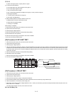
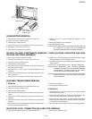
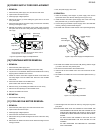
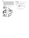
3. Discharge high voltage capacitor.
4. Push the lever of positive lock® connector.
5. Pull down on the positive lock® connector.
CAUTION: WHEN CONNECTING THE POSITIVE LOCK® CONNEC-
TORS TO THE TERMINALS, INSTALL THE POSITIVE
LOCK® SO THAT THE LEVER FACES YOU.
Figure C-1. positive lock® connector
[7] CONTROL PANEL ASSEMBLY REMOVAL
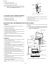
1. Disconnect the power supply cord and remove outer case.
2. Open the door and block it open.
3. Discharge high voltage capacitor.
4. Disconnect the leads from the control unit.
5. Remove the one (1) screw holding the control panel decoration to
the oven cavity front plate.
6. Remove the one (1) screw holding the control panel to the front
plate of the oven cavity.
7. Now, the control panel assembly is free.
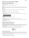
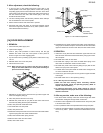
[8] GRAPHIC SHEET AND MEMBRANE SWITCH REPLACEMENT
1. REMOVAL
1. Disconnect the power supply cord and then remove outer case.
2. Open the door and block it open.
3. Discharge high voltage capacitor.
4. Remove the control panel assembly, referring to chapter of CON-
TROL PANEL ASSEMBLY REMOVAL.
5. Remove the three (3) screws holding the control unit to the control
panel frame. And remove the control unit.
6. Remove the rubber connector from the long slit on the control panel
frame.
7. Tear away the graphic sheet from the control panel frame.
8. Tear away the membrane switch from the control panel frame.
2. REINSTALL
1. Remove remaining adhesive on the control panel frame surfaces
with a soft cloth soaked in alcohol.
2. Tear the backing paper from the new membrane switch.
3. Insert the ribbon cable of the membrane switch into the slit of the
control panel frame.
4. Adjust the upper edge and right edge of the membrane switch to
the small depression on the surface of the control panel frame.
5. Attach the membrane switch to the control panel frame by rubbing
with a soft cloth not to scratch.
6. Tear the backing paper from the new graphic sheet.
7. Adjust the upper edge and right edge of the graphic sheet to the
large depression on the surface of the control panel frame.
8. Attach the graphic sheet to the control panel frame by rubbing with
a soft cloth not to scratch.
9. Tear the small backing paper from the ribbon cable of the mem-
brane switch.
10.Insert the two (2) hole of the ribbon cable into the two (2) pins of the
control panel frame (rear side).
11.Attach the ribbon cable to the control panel frame rear side.
12.Place the edge of the membrane switch’s ribbon cable on the lower
portion of the liquid crystal display.
13.Insert the rubber connector into the long slit on the control panel
frame.
14.Reinstall the control unit to the control panel frame with the three
(3) screws.
NOTE: Do not contact the conductor portion of the ribbon cable
(edge) and the rubber connector directly with your fin-
gers. This is to avoid oxidized.
Figure C-2. Graphic Sheet and Membrane Switch Replacement
Terminal
Push
Pull down
1
2
Lever
Positive lock¨
connector
Rubber connector
Conductor portions
Ribbon cable
of membrane
switch
Liquid crystal
display
Control panel frame
(Rear side)
Long slit
Pin
Graphic sheet
Membrane
switch
Small
depression
Large
depression
Small backing
paper
Ribbon
cable
Control panel frame
Slit