


34
Models 8752, 8756, 8757Operating Procedures
121218
Repeat Steps 1 through 7 for the other side of the
freezer on the Models 8756 and 8757.
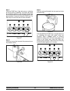
Step 8
Place the power switch in the OFF position before
disassembling the machine.
Disassembly
BE SURE THE POWER SWITCH IS IN THE
“OFF” POSITION TO ELIMINATE THE CHANCE OF
MOVING PARTS. CHECK TO MAKE SURE NO
LIGHTS ARE LIT ON THE CONTROL PANEL.
Step 1
Remove the handscrews, freezer door, beater(s),
shoes, scraper blades, and drive shaft(s) from the
freezing cylinder(s) and take them to the sink for
cleaning.
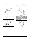
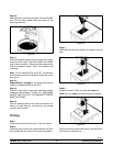
Step 2
Remove the air/mix pump. Unscrew the flare line from
the mix inlet tube. Disengage the pressure line from
the pressure switch and the mix inlet tube. Pull the
retaining pin out of the pump collar and slide the collar
down. Tilt the a ir/mix pump away from the machine
and take the entire assembly to the sink for further
disassembly and brush cleaning.
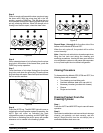
Step 3
Remove the pressure switch cap from the mix cabinet
and the diaphragm from the cap.
Repeat Steps 2 and 3 for the other side of the freezer
on the Models 8756 and 8757.
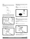
Step 4
Remove the front drip tray and splash shield.
Brush Cleaning
Step 1
Prepare a sink with an approved cleaning solution (ex-
amples: Stera SheenR or Kay- 5R). USE WARM WA-
TER AND FOLLOW THE MANUFACTURER’S SPE-
CIFICATIONS
If an approved cleaner other than Stera SheenR or
Kay- 5R is used, dilute it according to the label
instructions. IMPORTANT: Follow the labeldirections.
Too STRONG of a solution can cause parts damage,
while too MILD of a solution will not provide adequate
cleaning. Make sure all brushes provided with the
freezer are available for brush cleaning.
Step 2
Remove the seal(s) from the drive shaft(s).
Step 3
Remove the scraper blade clips from the scraper
blades.
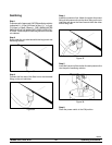
Step 4
From the freezer door(s) remove the gasket(s), front
bearing(s), pivot pin(s), draw handle(s), draw valve(s),
prime plug(s), and the design cap(s).
Remove all o- rings.
Note: To remove o- rings, use a single service towel
to grasp the o- ring. Apply pressure in an upward
direction until the o- ring pops out of its groove. With
the other hand, push the top of the o- ring forward. It
will roll out of the groove and can be easily removed.
If there is more than one o- ring to be removed, always
remove the rear o- ring first. This will allow the o- ring
to slide over the forward rings without falling into the
open grooves.
Step 5
Remove the flare line(s), suction line(s), retaining
pin(s) and mix inlet fitting(s) from the pump cylinder(s).
Remove the liquid valve body(ies) from the pump
cylinder(s).
Remove the piston(s) from the pump cylinder(s).
Remove all o- rings and check bands.
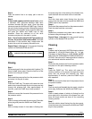
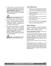
Step 6
Return to the freezer with a small amount of cleaning
solution. With the black bristle brush, brush clean the
rear shell bearing(s) at the back of the freezing
cylinder(s).
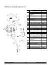
Figure 49