


15
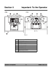
Models C708 & C716 Important: To the Operator
050628
System Data
System data is protected separately from the rest of
the data in m emory. System data includes variables
that change frequently such as the m ode the
machine is in, lockout status, serving counters, fault
codes, and others. While System Data is being
checked the following screen is displayed.
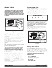
Initializing
System Data
If the System Data is corrupted, the machine is set
to OFF, the serving counters are set to zero, and the
faults are cleared. A “SYSTEM CRC ERR” fault is
set and displayed o n the VFD. An acknowledgement
(SEL key) is required.
Configuration Data
Configuration data is separate from the rest of the
data in the m emory. Configuration data is
information entered through operator and service
menus. While Configuration Data is being checked
the following screen is displayed.
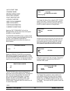
Initializing
Config Data
If Configuration data is corrupted, all user and
service settings are set to defaults. A “CONFIG
CRC ERR” fault is s et and displayed o n the VFD.
The system will continue to operate in its previous
mode but according to default settings.
Lockout Data
Lockout data i s protected separately from the rest of
the data in the memory. While the Lockout Data is
being checked, the following screen is dis played.
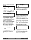
Initializing
Lockout Data
If Lockout Data is corrupted, all lockout history data
is cleared. A “LOCKOUT CRC ERR” fault i s
displayed.
After the memory integrity has been tested, the
Safety Timeout screen will be displayed.
Heat Cycle Data
Heat cycle data is checked separately from the rest
of the data in memory. Each individual Heat Cy cle
Data record is monitored for corruption individually.
At the start of a heat cycle, the next Heat Cycle data
record is cleared and data for the heat cycle is
writtentoit.ThecurrentHeatCycleDatais
displayed as the first heat cycle record in the HEAT
CYCLE DATA menu option.
The heat cycle data records are checked for integrity
when the record i s accessed, presently only through
the HEAT CYCLE DATA menu option. (For
additional Heat Cycle Data information,
see page 24.)
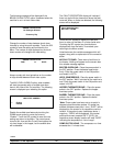
Once the system has initialized, the number of days
until brush cleaning is required is i ndicated on the
control panel. The S AFETY TIMEOUT screen will
be displayed with the alarm on for 60 seconds or
until any control symbol is touched.
SAFETY TIMEOUT
ANY KEY ABORTS
Power Switch OFF
After the safety timeout has been completed and the
power switch is OFF, the following screen is
displayed.
POWER SWITCH OFF
-=-=-=-=-=-
UNIT CLEANED