41
Models C708 & C716 Operating Procedures
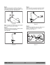
Step 7
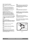
Once the cleaning solution stops flowing from the
door spout, close the draw valve and touch the
WASH symbol
, cancelling the WASH mode.
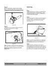
Repeat these steps on the other side of the
Model C716.
Disassembly
Note: Failure to remove the parts specified below
for brush cleaning and lubrication will result in
damage to the machine. These parts must be
removed e very 14 days or the m achine will lock out
and will not operate.
MAKE SURE THE POWER SWITCH IS IN
THE “OFF” POSITION! Failure to follow this
instruction may result in severe personal injury from
hazardous moving parts.
Step 1
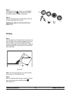
Remove the handscrews, freezer door, beater and
scraper blades, and drive shaft with drive shaft seal
from the freezing cylinder.
Step 2
Remove the scraper blade clips from the scraper
blades.
Step 3
Remove the drive shaft seal from the drive shaft.
Step 4
From the pump cylinder, remove the retaining pin,
mix inlet adaptor, valve cap, pump gasket, and the
piston. Remove the o-ring from the piston and valve
cap.
Step 5
Remove the freezer door gasket, front bearing, pivot
pin, draw handle, and draw valve. Remove the three
o-rings from the draw v alve.
Note: Remove the design caps (C716 only).
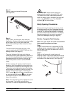
Step 6
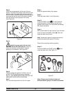
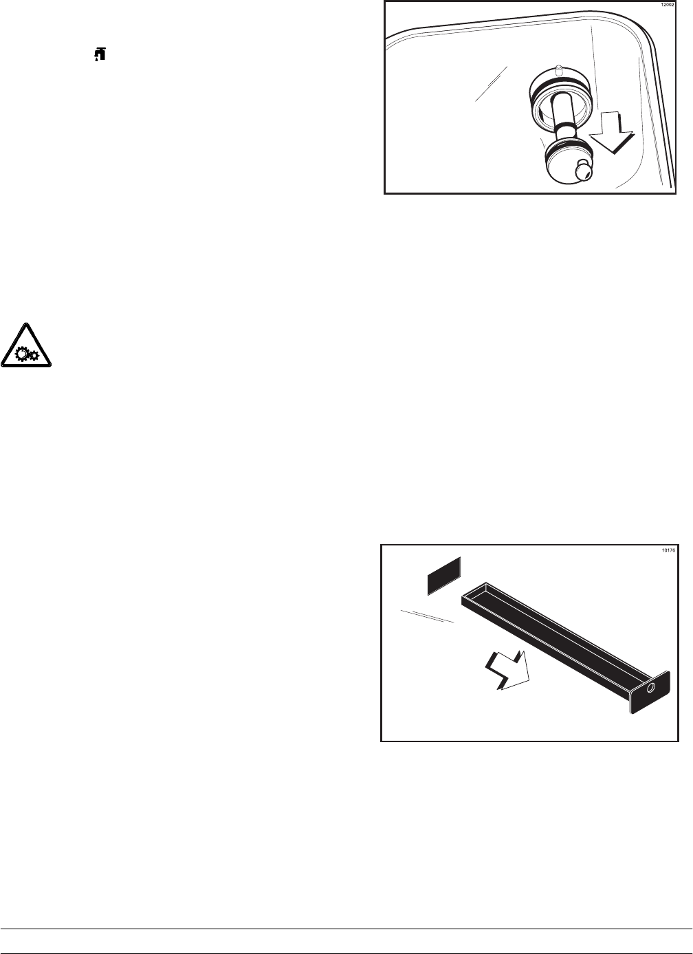
Remove the pump d rive shaft from the drive hub in
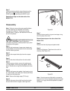
the rear wall of the mix hopper. (See Figure 58.)
Figure 5 8
Step 7
Remove the two small o-rings and one large o-ring
from the pump drive shaft.
Repeat these steps on the other side of the
Model C716.
Step 8
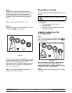
Remove the front drip tray and splash sh ield.
Step 9
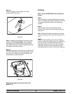
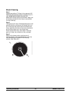
Remove all d rip pans . Take them to the s ink for
cleaning. (See Figure 59.)
Figure 5 9
Note: If the drip pans are filled with an excessive
amount of mix, it is an indication that the drive shaft
seal(s), or o-ring(s) should be r eplaced or properly
lubricated.


