


Model 2002 page 11
above, press the ZERO switch to display the decimation ratio (filtering). The larger the ratio, the
longer the response time.
EEPREEPR
EEPREEPR
EEPR
OM CalibraOM Calibra
OM CalibraOM Calibra
OM Calibra
tion Restoration Restora
tion Restoration Restora
tion Restora
tiontion
tiontion
tion
There are interlocks built into the CAL mode to minimize the chance of accidental alteration of the
calibration coefficients, but if calibration alteration does occur, the EEPROM calibration data can be
restored in the RUN mode by pressing the UP and DOWN switches simultaneously (RUN light will
flash), then press the “ZERO” switch, UP and DOWN switches (all three) simultaneously.
This will not correct the calibration if the tube has become contaminated or damaged. This reset will
not affect the gas selection, units or setpoints.
Also see units mode for default calibration restoration.
3.3 HIGH and LOW Set Point Modes
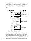
The Model 2002 provides TTL outputs for process control. The I/O cable is attached via a 9-pin
sub-D connector to the rear panel of the control unit. The pinout is shown in Figure 4.2.
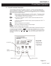
To view the high set point, place the Model 2002 in the HIGH mode by pressing the MODE switch
to illuminate the HIGH light and no other mode light. The display will show the set point selected.
During normal operation the alarm light will illuminate and the TTL output (pin # 3) will go high
(+5 V) if the pressure
exceedsexceeds
exceedsexceeds
exceeds the set point.
Similarly, to view the low set point access LOW mode by pressing the mode switch until the LOW
light is lit and no other mode light is illuminated. During normal operation, the LOW light will
illuminate and the LOW alarm TTL output (pin # 4) will go high (+5 V) if the pressure becomes
less less
less less
less than the set point.
The alarm lights cannot indicate an alarm condition while in the set point modes. Therefore, it is
advisable not to leave the instrument in these modes for extended periods.
To adjust a set point, press the mode switch until the set point is viewed. Then simultaneously press
the UP and DOWN switches. The active mode light will now flash indicating that the interlock has
been bypassed and the set point can be adjusted. The display shows the present set point.
Enter the new set point by using the UP and DOWN switches. Press and hold the UP switch to
increase the set point and the DOWN switch to decrease the setpoint. Allow a few seconds for the
circuitry to respond. If the button is held down for and extended period of time the adjustment rate
will start to increase. Release the button and press again to get finer control of the exact trigger
point.
At this point, the new set point is in temporary memory. If the instrument were unplugged now,
the Model 2002 would revert back to the original set point upon restarting. Return the 2002 to the
RUN mode to store the set point in permanent memory.
Once the interlock has been bypassed in the HIGH mode, it will stay active until the CAL mode is
entered. This will allow the user to set both setpoints without repeating the interlock bypass.
3.4 CAL Mode
Optimal performance of the Model 2002 is achieved by performing in situ adjustments to the
calibration coefficient in the CAL mode. There are three calibration coefficients. These are the zero
coefficient, the midrange coefficient and the atmosphere coefficient. Once a tube has been fully
calibrated the midrange coefficient should never need further adjustment, but it may be helpful to
adjust the zero coefficient or the atmosphere coefficient under certain situations. Even though the
operator inputs may be identical for adjustment of all three coefficients, microprocessor will detect