


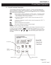

page 8 Model 2002
2.3 Transducer Installation
The transducer may be installed in any orientation. Although the transducer is rugged and will
perform well in many harsh environments, the tube should be installed in a clean and careful
manner. The tube is configured with the vacuum fitting requested. If your vacuum environment
is highly contaminated or has unique fitting requirements, a Hastings filter or special adapter may
be needed. Please contact the Hastings Instruments Sales Department for assistance in your
system configuration.
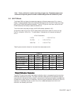
2.4 Control Unit Installation
EnEn
EnEn
En
vironment:vironment:
vironment:vironment:
vironment:
Indoor use
Altitude up to 2000 meters
Operating temperature range from 5
0
to 40
0
C
Maximum relative humidity: 80% for temperatures up to 31
0
C decreasing linearly to 50%
relative humidity at 40
0
C
Installation category II
PP
PP
P
anel Mount Instranel Mount Instr
anel Mount Instranel Mount Instr
anel Mount Instr
uctions:uctions:
uctions:uctions:
uctions:
The control unit can be panel mounted. See detail on page 43. The hole dimensions on the panel
are 3.62" x 3.62"(92.8mm x 92.8 mm). Slide the neoprene gasket that was shipped with the
control unit onto the case from the back. Slide the controller through the panel cutout. Hold the
hardware against the side and tighten the two screws.
TT
TT
T
ransducer Cable ransducer Cable
ransducer Cable ransducer Cable
ransducer Cable
Attachment:Attachment:
Attachment:Attachment:
Attachment:
The threaded connector attaches to the transducer. A finger tight connection is adequate for
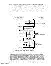
proper operation. The 9-pin male “D” connector attaches to the back panel (See Figure 4.2).
The transducer cable connects to the left hand connector when looking at the back.
I/O Cable I/O Cable
I/O Cable I/O Cable
I/O Cable
Attachment:Attachment:
Attachment:Attachment:
Attachment:
The mating male plug to the I/O connector is supplied with the unit. An I/O cable can be wired
with the 9-pin female “D” connector to use the analog output, digital alarms or the remote zero
functions. The connector will accept 20 gauge or smaller wire. The pinout is shown in Figure 4.2
(back panel figure). A detailed description of these pins is given in Section 4.
2.5 Initial Operation
Upon applying power to the control unit a pressure measurement will be given in Torr for nitrogen.
However, it is recommended that the user follow the instructions for zeroing and adjusting the
output at atmospheric pressure in Section 3.4 ("Cal Mode").