


Model 2002 page 9
Front Panel Operation
SECTION 3
3.1 Overall Functional Description
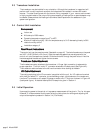
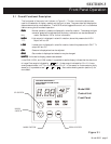
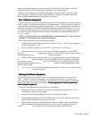
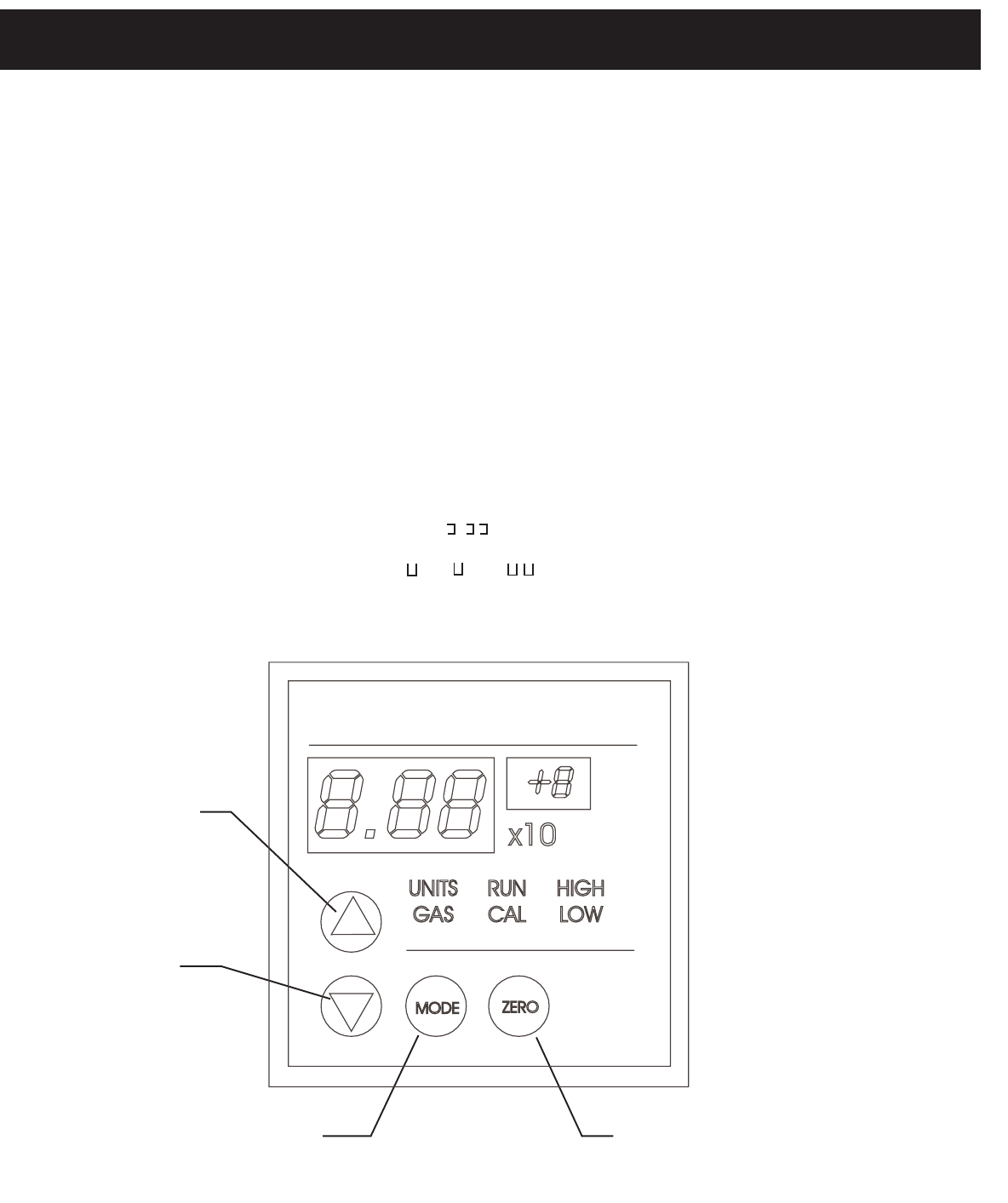
The front panel of the control unit is shown in Figure 3.1. The four circular blue buttons are
used for the selection of display readout and the input of data. The green data field displays the
data as determined by mode selection. The MODE switch toggles the control unit in a clockwise
fashion among the six modes of operation:
RR
RR
R
UNUN
UNUN
UN Normal operation, pressure is displayed in scientific notation. The analog to digital
converter speed can be adjusted and the factory calibration can also be restored in
this mode. See Section 3.2 for further information.
HIGHHIGH
HIGHHIGH
HIGH High set point is displayed in scientific notation, above this pressure the HIGH
TTL output will be +5V.
LOLO
LOLO
LO
WW
WW
W Low set point is displayed in scientific notation, below this pressure the LOW TTL
output will be +5V.
CALCAL
CALCAL
CAL Pressure is displayed and can be adjusted.
GASGAS
GASGAS
GAS Gas number is displayed and selection may be changed.
UNITSUNITS
UNITSUNITS
UNITS Units used to display pressure are selected.
In the RUN, HIGH, and LOW modes, it is possible to see the display indicate that the data is out
of range. Overrange is indicated by . x10
-
. Underrange is indicated by 0.0 x10
-
. A mea-
sured pressure below 1x10
-4
Torr is indicated by 0.0 x10
+
. In the case of an unconnected or faulty
sensor(s), it is possible to see “ .“, “. “ or “ . “. See trouble shooting section (section 8) for
more detail.
Model 2002 Control Unit Front Panel
Figure 3.1
UP SWITCH
DOWN
SWITCH
MODE SWITCH ZERO SWITCH
mbar
Torr
Pa
HASTINGS INSTRUMENTS
DUAL SENSOR VACUUM GAUGE
MODEL 2002
Model 2002
Control Unit
Front Panel