


page 20 Model 2002
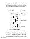
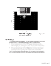
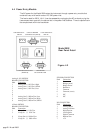
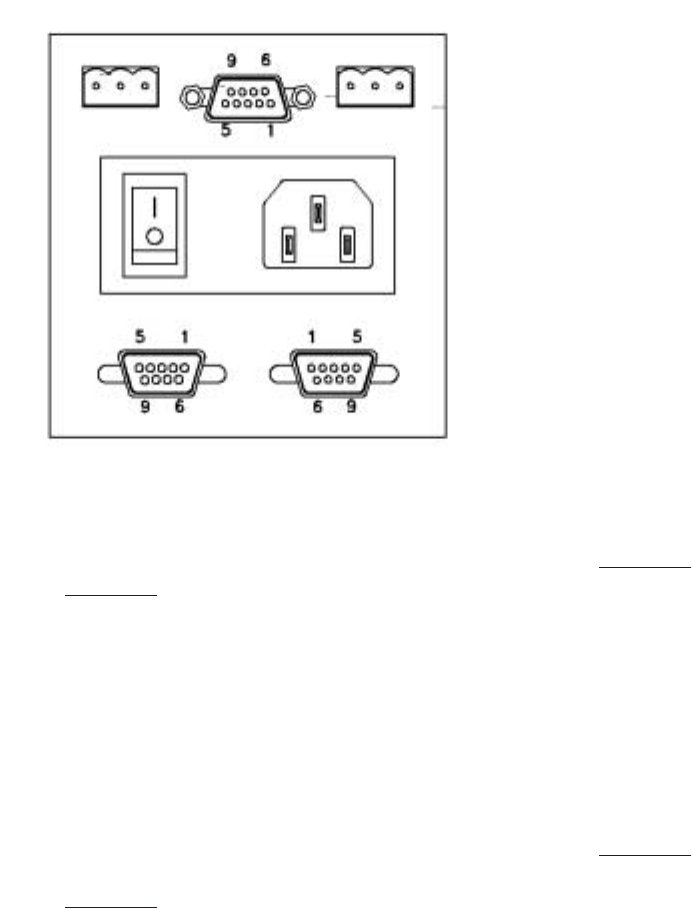
Figure 4.2
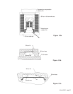
SENSOR CONNECTOR
Pin# Connection
1 Sensor
2 Bridge (sense)
3 Bridge-Power
4 Reference
5 Common
6 Common (sense)
7 N/C
8 N/C
I/O CONNECTOR
Pin# Connection
1 Analog Output
2 Analog Common
3 High Setpoint
4 Low Setpoint
5 Digital Common
6 Remote Zero
7 +5V
Model 2002
Rear Panel Detail
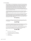
4.4 Power Entry Module
The AC power for the Model 2002 enters the instrument through a power entry module that
contains a fuse, on/off switch and an IEC 320 power inlet.
The fuse is rated for 250 V, 1/4 A. It can be accessed by unplugging the AC cord and prying the
fuse compartment open with the tab and slot in the power inlet chamber. There is a spare fuse in
the compartment within the fuse holder.
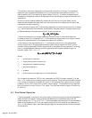
Analog 0-10V OPTION
BOARD CONNECTOR
Pin# Connection
1 Analog Out 1 (1024 Torr) High
2 Analog Out 1 (1024 Torr) Shield
3 Analog Out 1 (1024 Torr) Low
4
5
6
7 Analog Out 2 (1000 mTorr) Low
8 Analog Out 2 (1000 mTorr) High
9 Analog Out 2 (1000 mTorr) Shield
4-20mA OPTION
BOARD CONNECTOR
Pin# Connection
1 I-Loop Out (+) 1024 Torr
3 I-Loop In (-) 1024 Torr
8 I-Loop Out (+) 1000 mTorr
7 I-Loop In (-) 1000 mTorr
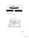
LOW SETPOINT OPTION BOARD HIGH SETPOINT
RELAY CONNECTOR (MALE) RELAY
TRANSDUCER CONN. STANDARD
(FEMALE) I/O CONNECTOR