


page 24 Model 2002
5.2 Pirani Sensor
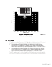
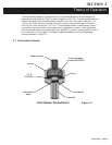
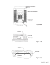
Figure 5.3a shows a thin film Pt resistive element on a one micron thick Si
3
N
4
continuous mem-
brane surrounded by a thin film Pt reference resistor on a Si substrate. The membrane is heated
to a constant 8
0
C above ambient temperature that is monitored by the substrate resistor. The
membrane resistor is approximately 60 Ω and a constant substrate to membrane resistance ratio
is maintained at 3.86. Figure 5.3b shows the Pirani die in cross section. A parallel Si lid is
eutectically bonded to the Au pads and sits 5 microns above the membrane. As shown, this
dimension gives a Knudsen number of greater than 0.01 up to atmospheric pressure, which
insures a molecular flow component. At 10 Torr the region above the membrane is totally in the
molecular flow regime and thus provides a relatively linear output verses pressure overlapping the
linear output versus pressure of the piezo.
The measurement technique is to produce an output signal that is proportional to the power
supplied to the heated resistor by using the product of the current and voltage. This rejects errors
introduced by resistance changes since the sensor resistance is no longer part of the power
equation.
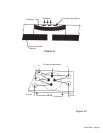
A signal proportional to the power is obtained by multiplying the voltage across the heated sensor
and the voltage impressed by the direct current across a constant series resistance. The power
supplied to the sensor resistor must equal the heat dissipated (E
t
). The three main heat loss
routes from the heated sensor are thermal conduction through the silicon nitride membrane to the
silicon substrate (E
s
) radiation losses (E
r
) and thermal conduction through the gas to the silicon
substrate (E
g
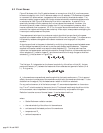
); thus, as shown in Figure 5.3c,
EE
EE
E
tt
tt
t
= E = E
= E = E
= E
ss
ss
s
+ E + E
+ E + E
+ E
rr
rr
r
+ E + E
+ E + E
+ E
gg
gg
g
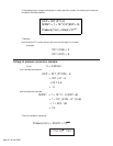
The first term, E
s
, is dependent on the thermal conductivity of the silicon nitride (K), the tem-
perature difference (∆T) between the heater and silicon substrate and geometric factors (A
M
&
L). E
S
is given by
EE
EE
E
ss
ss
s
= (K = (K
= (K = (K
= (K
∆∆
∆∆
∆
T T
T T
T
AA
AA
A
mm
mm
m
)/L)/L
)/L)/L
)/L
A
m
is the membrane cross sectional area through which the heat transfer occurs. This is, approxi-
mately, the outer circumference of the membrane multiplied by the membrane thickness. L is the
distance from the edge of (Rs) the heated sensor resistor to the silicon substrate.
For any particular sensor, all of the factors, except ∆T, are constants dependent on its construc-
tion. The ∆T is held constant by the control circuit. The thermal loss through the silicon nitride
will be a constant value independent of the thermal conductivity and pressure of the gas.
Radiation is another source of thermal losses. It can be determined from
EE
EE
E
rr
rr
r
= =
= =
=
σεσε
σεσε
σε
(T(T
(T(T
(T
hh
hh
h
44
44
4
-T-T
-T-T
-T
aa
aa
a
44
44
4
)A)A
)A)A
)A
ss
ss
s
where
σ = Stefan-Boltzmann radiation constant
ε = thermal emissivity of the silicon nitride membrane
A
S
= surface area of the heated portion of the membrane
T
h
= temperature of R
s
T
a
= ambient temperature