


page 30 Model 2002
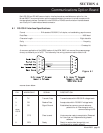
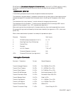
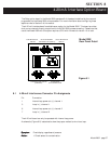
6.2 Interface Connector Pin Assignments for RS-232
Note: an alternate method of connecting to a 2 wire bus is to leave the interface configured for
full duplex and externally connect pins 2 and 3 to the(+) bus and pins 4 and 8 to the (-) bus.
6.3 Operation of the Serial Interface
Communication with the serial interface of the Model 2002 is via an ASCII data string. In the RS-232
mode the command message consist only of a command string and the terminator. The attention
character and address string are not required, but if they are used they MUST be valid. If all compo-
nents of the ASCII data string are valid the command will be accepted and executed. The RS-232
mode is sometimes referred to as point-to-point mode since only one device may be connected to the
controller at any given time.
A message to the Model 2002 in the RS-485 mode consist of an attention character followed by
the address string , the command string, and the terminator. If all components of the ASCII data
string are valid the command will be accepted and executed. The RS-485 mode is also referred to
as multipoint mode since up to 31 devices may be connected to the same controller in a network
scheme.
The RS-485 address may be display on the model 2002 front panel (with software verson 1.60 or
higher). Press the MODE switch until the units field is lit, press both the UP nad DOWN
switches simultaneously. The units light will now flash. Press the ZERO switch to display the
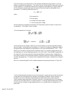
PIN MNEMONIC SIGNAL DESCRIPTION
2 TX+ Transmit + Differential data
signal levels to
8 TX - Transmit - the RS-485 bus
3 RX+ Receive + Differential data
signal levels from
4 RX- Receive - the RS-485 bus
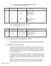
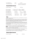
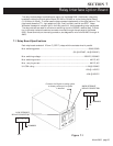
6.2.1 Interface Connector Pin Assignments for RS-485
(full duplex-4 wire)(jumper position 2-3).
}
}
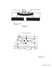
PIN MNEMONIC SIGNAL DESCRIPTION
2 TX+/RX+ Transmit +/Receive + Differential data
signal levels to and from
8 TX-/RX- Transmit -/Receive - the RS-485 bus
6.2.2 For RS-485 (Half Duplex - 2 wire)
(jumper position 1-2).
}