


– 27 –
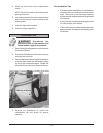
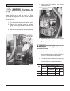
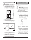
Disconnect the
electrical power to the machine and
follow lockout / tagout procedures.
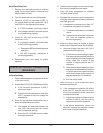
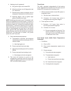
1. Remove the blower motor and mounting
assembly as outlined under Blower and
Motor in Removal and Replacement of Parts.
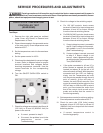
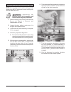
2. Loosen the motor mounting bolts.
3. Adjust the motor position until the blower is
parallel to and
1
/4" inch away from the motor
mounting plate. Check to see if the blower is
square to the motor mounting plate at the
top, bottom, left and right of the blower.
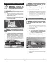
A. If the blower is square, then tighten
motor mounting bolts and proceed to
step 4.
B. If the blower is not square, continue
adjusting until proper spacing is achieved
then tighten motor mounting bolts. If
necessary, place shims between motor
and frame.
4. Reverse the procedure to install. Use
locktight on mounting nuts and bolts.
BLOWER ADJUSTMENT
MOTOR MOUNTING PLATE
PLACE SHIMS UNDER FRONT OF
MOTOR TO WIDEN BOTTOM SPACE.
PLACE SHIMS UNDER REAR OF
MOTOR TO WIDEN TOP SPACE.
BOTTOM
TOP
PLACE SHIMS HERE
WHEN NEEDED.
FLAT
WASHER
MOTOR
FRAME
FLAT WASHER
NUT/STAR
WASHER
1/4 INCH AT
ALL PLACES
BLOWER
PL-56058
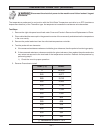
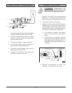
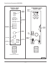
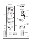
1. Use a Microampere (µamp) meter to measure
the flame current on both wires S1 & S2.
2. Connect a Microampere meter as shown
above to S1 & S2, to read the actual flame
current of each igniter.
3. The ignition system is 1 µamp sensitive.
4. You should be able to attain a reading of 4
µamps when connected as shown.
5. The meter is to be placed in series with the
flame sense wires S1 & S2.
6. Connect at the board or the igniter end,
whichever is more convenient.
FLAME CURRENT MEASUREMENT
S1
S2
56
59
48
57
LEFT RIGHT
Y
BURNER BURNER
52
57
S1
8
X
D
S2
56
C-2
123
U
345519-4
424471-G1
2
2
1
TH
3
55
LED
DUAL
INDICATOR
DIAGNOSTIC
MODULE
IGNITION
CHANNEL
FC1-
FC1+
OUT
SPARK
FC2-
FC2+
S2
S1
V2
W
NC
V1
OUT
SPARK
RED
GND
24V
FENWAL
T
L
2
L2L1
1
W
PLUG.
WHITE
BLACK
GREEN
48
6
V
GND.
AB
46
5
120 VOLT UNITS PROVIDED
WITH 3 PRONG GROUNDED
AB
417856-1
CONNECT 200-240 VOLT
SUPPLY TO L1 & L2
10
4
MICROAMP METER