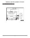
– 7 –
COVERS AND PANELS
Disconnect the
electrical power to the machine and
follow lockout / tagout procedures.
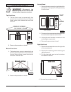
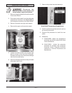
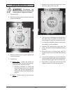
Top Front Cover
1. The top front cover is secured with four
screws, two on each side of cover. Remove
these screws, then remove the cover from
the oven.
2. Reverse the procedure to install.
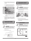
Bottom Front Cover
1. The bottom front cover is secured with six
screws, two on each side of cover and two on
the top. Remove these screws then remove
the cover from the oven.
2. Reverse the procedure to install.
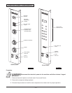
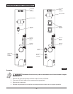
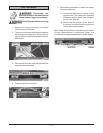
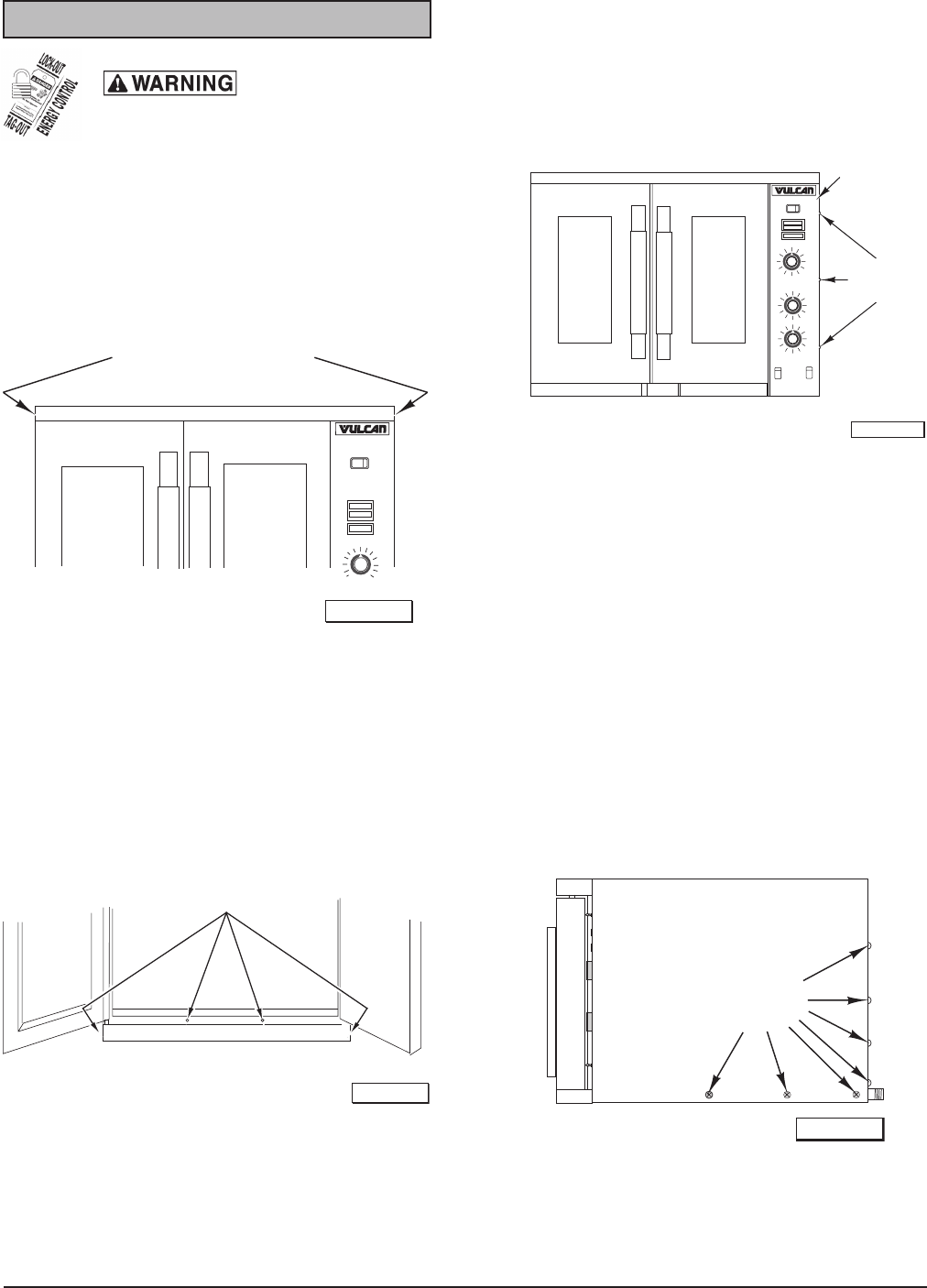
Control Panel
1. Remove three screws on the right side which
secure the control panel. Pull the panel away
from the oven.
2. Disconnect the temperature probe leads from
the solid state temperature controller.
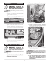
3. Unplug the wire harness connector to the
control panel components.
4. Reverse the procedure to install.
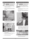
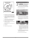
Right Side Panel
1. Remove the screws that secure the right side
of the control panel.
2. Remove the remaining screws securing the
right side panel.
3. Pull the right-side panel out at the bottom
then down to remove.
4. Reverse the procedure to install.
RIGHT SIDE
RIGHT SIDE
REMOVE
REMOVE
SCREWS
SCREWS
PL-56043
TOP FRONT COVER
REMOVE SCREWS
PL-56040
O
F
F
OVEN
COOL
M
AST
ER
SW
IT
CH
ON
HEAT
IGNITION
REMOVE
SCREWS
CONTROL
PAN EL
ON
HI
OFF
LOW
LIGHTS
FAN SPEED
SG4D SHOWN
TH
ERMO
ST
AT
POWER
LEVE
L
OFF
OV
E
N
COOL
MA
STER
SWITC H
PL-56042-1
BOTTOM FRONT COVER
BOTTOM FRONT COVER
REMOVE SCREWS
REMOVE SCREWS
PL-56041


