


– 36 –
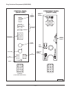
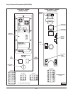
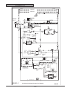
C. Power to terminal 1 on solid state relay 1
SSR1-load side and solid state relay 2
SSR2-load side.
D. Component cooling fan energized.
E. Transformer (T1) is energized, 24 volt
output.
1) Power (24 VAC) to one side of the
following components: heat relay (R1)
normally open (N.O.) contacts, high
limit connected through the normally
closed (N.C.) contacts to the first
valve (safety) on the dual solenoid
gas valve.
2) First valve (safety) on the gas valve
energized. Gas does not flow to the
burner until the second valve (main)
is energized.
3) Ignition module energized.
4) Power (24 VAC) to the oven computer
control.
3. Control is energized and performs a power on
self test before energizing outputs. If the
control passes self test, then the outputs are
energized and operation sequence continues,
If control does not pass self test, then the
corresponding error code is displayed.
NOTE: Control retains last temperature set.
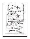
A. Computer control senses oven cavity
temperature.
1) With the oven cavity temperature
below set point, the controls
120 VAC output from pin C3-2 is
activated and power is connected to
the common (C) side of the blower
switch contacts on the convection
fan motor.
2) The controls 5 VDC output from pins
C2-2 (-) and C2-8 (+) is activated and
SSR1 relay is energized.
a. Convection fan motor is
energized (fan speed on HI).
3) When the convection fan motor
reaches operating speed:
a. The blower switch (N.O.) on the
motor closes.
B. Heat relay coil (R1) energized.
1) (R1) contacts (N.O.) close and the
heating circuit is powered.
2) Oven heat light on the control comes
on.
C. Ignition module is energized.
1) Heating circuit is powered.
2) No ignition light (red) comes ON.
3) Module performs a self-diagnostic
test for 4 seconds.
4) Second valve (main) on the gas valve
is energized. Gas starts to flow to
burners.
5) Sparking begins, the no ignition light
goes out and burners light.
NOTE: Sparking continues for up to 7 seconds or until
a flame is established on both burners. If a flame is
sensed on both burners, the no ignition light stays out
and burner remains lit. If a flame is not sensed on both
burners after 7 seconds of sparking, the no ignition
light comes back on, second valve (main) on the gas
valve is de-energized and gas flow to the burner
stops. Ignition trial cycle repeats after a 15 second
purge between cycles for two additional tries before
locking out. To reset after a lockout, turn power
switch (S1) OFF then ON.
4. Oven reaches set point temperature.
A. Computer control deactivates the
120 VAC output to heat relay (R1).
1) Heat relay (R1) de-energized and the
normally open (N.O.) contacts open.
B. Power removed from ignition control
module.
1) The second valve (main) on the gas
valve is de-energized and gas flow to
the burner stops.