


ELECTRIC COMBI OVEN - REMOVAL AND REPLACEMENT OF PARTS
Page 16 of 68
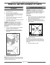
Sealing Washer
1. Remove the right side panel as outlined under
“COVERS AND PANELS”.
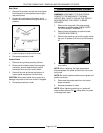
2. Open the oven door and remove the rack
guide, filter and exhaust assembly as outlined
under “RACK GUIDE/FILTER/EXHAUST
ASSEMBLY”.
WARNING:
THE FOLLOWING STEPS REQUIRE
POWER TO BE APPLIED TO THE UNIT DURING
THE ADJUSTMENT. USE EXTREME CAUTION AT
ALL TIMES.
3. Reconnect the electrical power to the machine
at the main circuit box.
4. Close the door, turn the oven ON and press the
Start/Stop button.
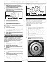
5. Observe the rotation of the vent motor cam.
When the cam stops turning then the vent
should be closed.
NOTE
: When the oven is turned OFF or the door is
opened, the vent should open automatically.
6. Disconnect the electrical power to the machine
at the main circuit box. Place a tag on the
circuit box indicating the circuit is being
serviced.
NOTE
: Power to the oven must be removed in this
manner. If the oven is turned OFF or the door is
opened, the vent will re-open automatically.
7. Open the oven door and examine the vent from
inside the cavity.
A. If the mounting nut is visible, proceed to
step 8.
B. If the mounting nut is not visible, then the
vent needs to rotate 180 degrees.
Reconnect power to the machine and
repeat steps 3 through 7A.
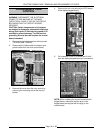
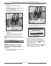
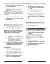
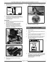
8. Remove the nut securing both shutters and the
sealing washer to the shaft extension rod then
remove the shutters and sealing washer.
9. Install new sealing washer and re-assemble.
Shaft Extension
1. Remove the left, right and rear panels as
outlined under “COVERS AND PANELS”.
2. Open the oven door and remove the rack
guide, filter and exhaust assembly as outlined
under “RACK GUIDE/FILTER/EXHAUST
ASSEMBLY”.
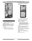
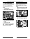
3. Remove the screw and nut behind the motor
assembly that connects motor to shaft
extension rod.
4. Rotate the extension rod approximately 90
degrees by hand.
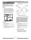
5. Examine the vent from inside the cavity.
A. If the mounting nut is visible, proceed to
step 6.
B. If the mounting nut is not visible, then the
extension rod needs to rotate
approximately 90 degrees more.
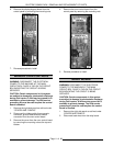
6. Remove the nut securing both shutters and the
sealing washer to the extension rod then
remove the shutters and sealing washer.
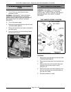
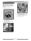
7. Remove the shutter screw from the extension
rod.
8. Release the snap ring on the left end of the
shaft (if facing oven) and pull shaft extension
out.
NOTE
: If the washers on the exterior of the vent
housing come loose, red silicone must be re-applied
to prevent steam leakage above the oven cavity.
9. Reverse procedure to install.
WATER LEVEL SENSORS AND
WATER EQUALIZATION TUBE
1. Turn the oven off and allow steam generator
tank to drain.
WARNING:
DISCONNECT THE ELECTRICAL
POWER TO THE MACHINE AT THE MAIN
CIRCUIT BOX. PLACE A TAG ON THE CIRCUIT
BOX INDICATING THE CIRCUIT IS BEING
SERVICED.
2. Turn off the water supply.
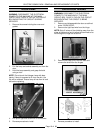
3. Remove the right side panel as outlined under
”COVERS AND PANELS”.
4. Disconnect lead wires and hose clamps from
the water equalization tube.
NOTE
: Some water will continue to drain out.