


Page 2-1
2-1
Cooking Products Service Manual
Original July, 1996 4321891
© 1996 Whirlpool Corporation
THEORY OF OPERATION
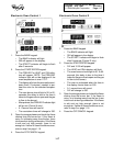
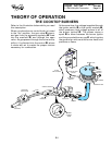
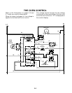
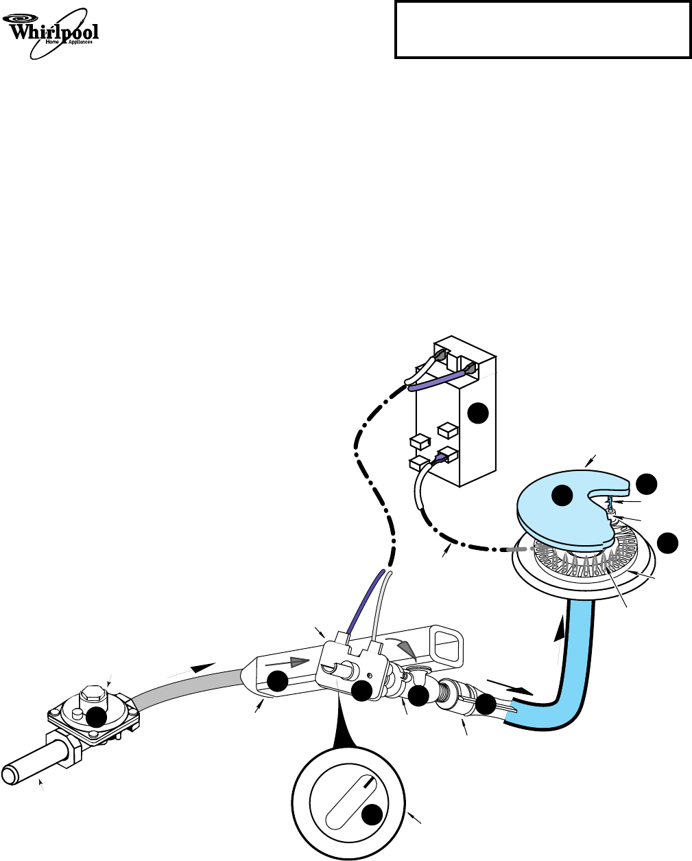
THE COOKTOP BURNERS
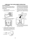
Refer to the illustration below while you read
this description.
When a surface burner control knob is turned
to the “lite” position, the gas valve r opens,
and gas from the pressure regulator s flows
into the manifold t, and through the open
valve. As gas passes through the valve and its
orifice, it is directed into the venturi u, where
it mixes with air to create the proper mixture
necessary for combustion.
At the same time, line voltage is applied through
the ignitor switch v to the ignitor module w,
which produces high-voltage pulses to all of
the burner ignitors x. The pulses cause a
spark y to occur between the burner ignitor
and the grounded burner cap z, which ignites
the gas and air mixture at the burner head, and
produces a flame.
PRESSURE
REGULATOR
GAS INLET
IGNITOR
MODULE
VENTURI
GAS VALVE
IGNITOR SWITCH
BURNER
CONTROL
KNOB
GAS
MANIFOLD
BURNER
IGNITOR
BURNER CAP
TO BURNER
IGNITOR
SPARK
BURNER
BURNER FLAME
GAS FLOW
120 VAC
LINE VOLTAGE
GAS FLOW
HIGH VOLTAGE
PULSES
OFF
LITE
4
7
9
8
10
2
5
6
1
3