


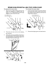
2-4
TROUBLESHOOTING THE IGNITOR SYSTEM
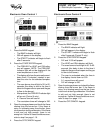
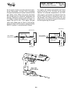
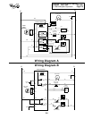
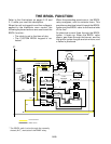
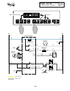
PROGRAM DIAGRAM A DIAGRAM B
Bake P3-1 to P2-1 P2-3 to P2-4
Broil P3-1 to P2-1 P2-2 to P2-1
Diagram A—Bake:
With the EOC programmed
for the Bake mode, you should obtain a read-
ing of 120 VAC between P3-1 and P2-4, and
between P3-4 and P2-1.
Diagram A—Broil:
With the EOC programmed
for the Broil mode, you should obtain a read-
ing of 120 VAC between P3-2 and P2-1, and
between P3-1 and P2-2.
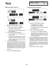
Diagram B—Bake:
With the EOC programmed
for the Bake mode, you should obtain a read-
ing of 120 VAC between P2-4 and Neutral.
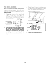
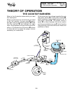
L1
N
ELECTRONC OVEN CONTROL
IGNITOR
BURNER
DUAL GAS
SAFETY VALVE
BAKE
HR MIN
CUSTOM
BROIL
AUTO
CLEAN
CLOCK
TIME
DELAY
TIMER
SET
STOP
TIMER
OFF
OFF
CANCEL
START
ENTER
5 SEC
HEAT BAKE BROIL LOCKED CLEAN TIMER
O
F
ON
350
10:30
AB
C
D
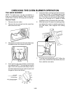
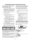
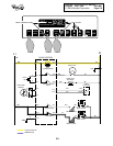
Ignitor Glows With No Ignition
1. Check that gas is turned on to the range.
2. Turn the power on and set the thermostat
to 350˚F.
3. Check the ampere draw at the bimetal
valve.
a) Using a wraparound ammeter, test one
leg for ampere draw at "D" or "C".
1. NORTON (flat) Ignitor - 3.2 to 3.6
amps.
2. CARBORUNDUM (round) Ignitor-
2.5 to 3.0 amps.
If the ampere draw is NOT within the
proper range, replace the ignitor.
b) If the correct ampere draw is present,
replace the valve.
For safety purposes, when measuring the
current flow through the ignitor circuit, shut
off the main, or the oven gas shut-off valve.
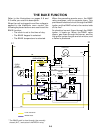
NOTE: A simple circuit is shown. The actual
circuit may include fuses, clock, selector
switch, or other items.
Diagram B—Broil:
With the EOC programmed
for the Broil mode, you should obtain a read-
ing of 120 VAC between P2-1 and Neutral.
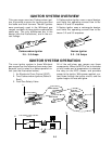
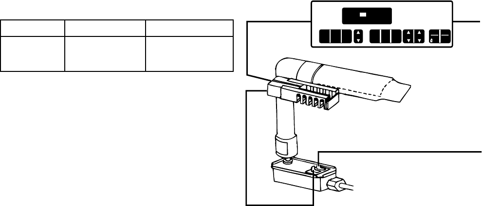
Refer to the illustration below while you read
the following troubleshooting information.
Ignitor Does Not Glow
1. Disconnect or remove the ignitor and mea-
sure its resistance. Cold resistance should
be between 50 and 150 Ohms. (The value
of the resistance is not important as long
as the ignitor is not open or shorted).
2. Check the internal fuses, switches, and
120 VAC power supply.
3. If power is working:
a) Disconnect the oven power and re-
move wires at “B” and “C”.
1. Check continuity between wire “B”
and terminal “C”. If continuity is
present, go to Step 4.
b) If continuity is NOT present, remove
wire at “D” and probe terminals “D”
and “C” for continuity. If NO continu-
ity, replace the bimetal valve.
c) If continuity is present at “D” and “C”,
probe wires “B” and “D”. If NO continu-
ity, replace the ignitor.
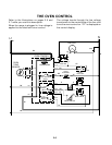
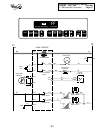
4. Check for
120 VAC
at the following loca-
tions, and the relay(s) on the Electronic
Oven Control you are servicing. Also re-
fer to the wiring diagrams on the next
page.