


15628-9-1007 Page 11
Assembly of Stove Casting
(Figures 7, 8, 9, 10, 11, 12 and 13)
Attention: Included in the hardware package are (8) 1/4" inside
diameter washers. A 1/4" washer may be used with a 1/4-20 x 3/8"
bolt when assembling the stove casting parts. If a bolt hole is not
tapped deep enough for a tight fit between stove casting parts, the
1/4" washer can be used as a shim to provide a tight fit.
The 1/4" washers are not required for assembly of the stove casting
if all the bolt holes are tapped to a proper depth.
Additonal 1/4" washers are to be purchased locally.
1. Place porcelain casting pieces on a non-abrasive surface
in order to protect the porcelain finish. The exterior of the
porcelain casting pieces should be facing the non-abrasive
surface.
2. The assembly of the casting is accomplished in 7 stages:
A. Attaching legs to the sides (Figure 7).
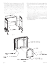
B. Attaching rear cover to sides (Figure 8).
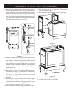
C. Removing protective packaging from casting front and
window (Figure 9).
D. Assembly of front by attaching retaining tabs and placing
front on unit (Figure 10).
E. Inserting firebox into partially completed assembly (Figure
11 and Figure 12).
F. Attaching firebox to rear cover (Figure 13).
G. Placing top on unit.
Detailed Instructions Follow
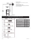
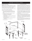
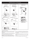
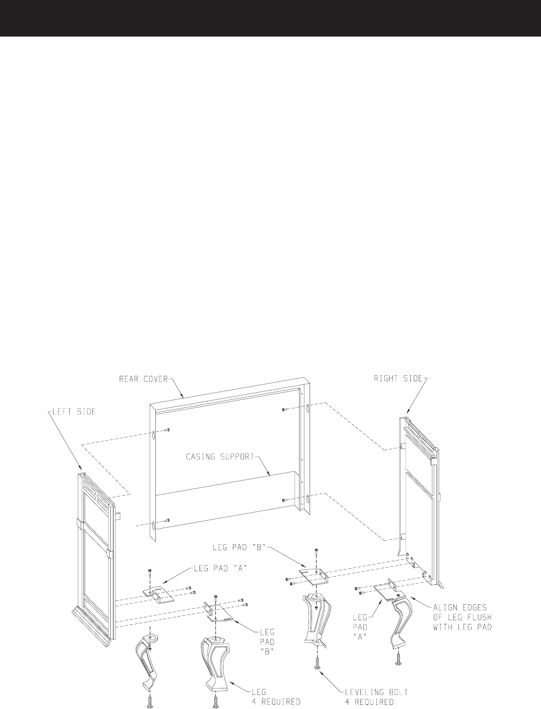
3. Refer to Figure 7, the leg pads will have the letter "A" and "B"
stamped into the metal. Place leg pad "A" and leg pad "B" at
the bottom of each casting side. Leg pad "A" attaches to the
front of the casting side, right and to the rear of the casting
side, left. Leg pad "B" attaches to the rear of the casting side,
right and to the front of the casting side, left. Position the 3/4"
flange on the leg pad against the (2) locator dimples on the
casting side. The 3/4" flange must be facing upward, toward
the top louver openings on the casting side. Attach the two rear
leg pads to the casting sides with (2) 3/8" bolts. Attach but do
not completely tighten the two front leg pads to the casting
sides with (2) 3/8" bolts. Attention: The front leg pads can
be adjusted to provide a snug fit between the casting front and
the casting sides.
4. Attach (4) leveling bolts to the bottom of the (4) legs.
5. Align the 3/8" hole at the top of the leg with the 3/8" hole in
the leg pad. Attention: For proper positioning of the leg to the
leg pad the (2) 1-1/2" top edges of the leg must be placed flush
and parallel to the (2) edges on the leg pad. Attach leg to leg
pad by inserting (1) 1" bolt through the leg pad and into the
leg, secure bolt with 1/4" nut.
6. Insert (2) 3/8" bolts into the (2) holes on the edges of the
casting sides. The bolts should only be threaded half-way into
the holes in order to allow for clearance when the casting back
is attached to the casting sides.
Figure 7
ASSEMBLY OF STOVE CASTING