


15628-9-1007Page 24
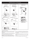
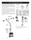
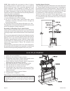
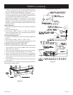
Installing Support Brackets
A horizontal pipe support MUST BE used for each 3 feet of horizontal
run. The pipe supports should be placed around 6-5/8 inch diameter
pipe and nailed in place to framing members. There MUST BE a 2
inch clearance to combustibles above 6-5/8 inch diameter pipe and
elbows and 1 inch clearance on both sides and bottom of 6-5/8 inch
to combustibles on all horizontal pipe sections and elbows.
Vertical runs of this vent systems must be supported every 4 feet
above the appliance flue outlet by wall brackets attached to the
6- 5/8 inch vent pipe and secured with nails or screws to structural
framing members.
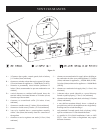
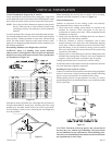
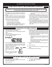
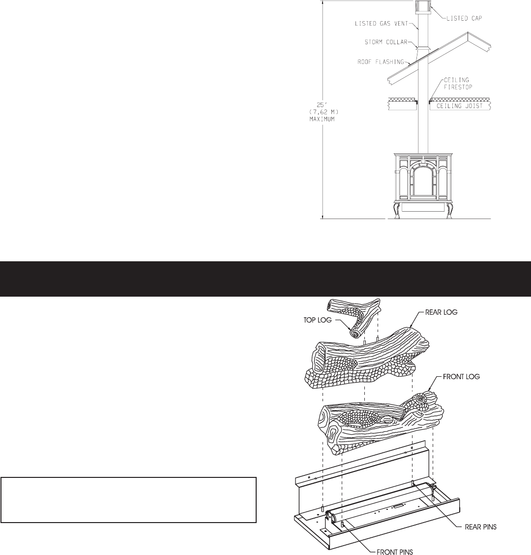
1. Lower valve cover on firebox.
2. Release two door latches at bottom of firebox.
3. Grasp bottom of glass frame, lift glass frame upward in order
to release glass frame from lip on top of firebox.
4. Remove logs from interior of firebox. Remove all protective
packaging from logs and interior of firebox.
5. Place front log onto two (2) front pins on inner bottom.
6. Place rear log onto two (2) pins on rear log support.
7. Place top log onto two (2) pins on rear log.
8. Align and place top of glass frame over lip on top of firebox.
Grasp bottom of glass frame, push inward and place glass
frame onto firebox.
9. Attach two door latches to bottom of firebox.
10. Log placement is completed.
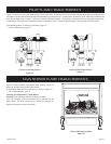
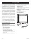
Refer to Figure 34 for the following warning.
Warning: Failure to position the parts in accordance with
this diagram or failure to use only parts specifically approved
with this appliance may result in property damage or personal
injury.
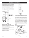
NOTE: When installing this vent system in a chase, it is always
good building practice to insulate the chase as you would the
outside walls of your home. This is especially important for cold
climate installations. Upon completion of building your chase
framing, install the vent system by following the instructions in
this manual. Remember to build the chase large enough so that
minimum clearance of combustible materials (including insulation)
to the vent system are maintained.
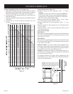
Vertical Through the Roof Applications
Your Gas Fireplace has been approved for
a) Vertical installations up to 25 feet in height.
b) Two sets of 45 degree elbow offsets within these vertical
installations. From 0 to a maximum of 8 feet a vent pipe can
be used between elbows.
c) Wall straps must be used to support offset pipe every 4 feet.
This applications will require that you first determine the roof pitch
and use the appropriate venting components.
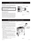
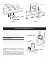
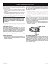
Reassembly and Resealing Vent-Air Intake System
Attach vent elbow to appliance air drop with (4) 1/2" hex-head screws
in either the vertical or horizontal position, replace horizontal and
vertical pipe lengths, elbows and horizontal or vertical termination
kit.
All vent system components lock into place by sliding the concentric
pipe section with four (4) equally spaced interior beads onto the
appliance collar or previously installed component end with four
(4) equally spaced indented sections. When the internal beads
of each starting 6-5/8 inch outer pipe line up, rotate pipe section
clockwise 90° (approximately 3 inches). The vent pipe is now
locked together.
Continue replacing components per the vent system configuration.
Be certain that each succeeding vent component is securely fitted
and locked into the preceding component in the vent system.
Figure 34
LOG PLACEMENT
Figure 33