


15628-9-1007 Page 17
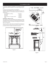
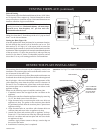
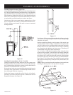
Sidewall Venting
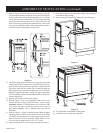
The maximum vertical and horizontal distances for one (1) 90° elbow
are 25 feet and 12 feet, respectively. Vertical dimensions are based
on top of fireplace to centerline of pipe. Horizontal dimensions are
based on centerline of pipe to termination.
CAUTION: Total vertical run MUST BE completed before
starting horizontal run. Horizontal chimney run must slope
upward (away from fireplace) 1/4" per foot and vent
termination must be level.
Under no circumstances should combustible materials (including
siding) be closer than 2" from the top of the 6 5/8" pipe or closer
than 1" on the side and bottom.
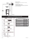
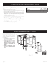
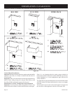
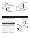
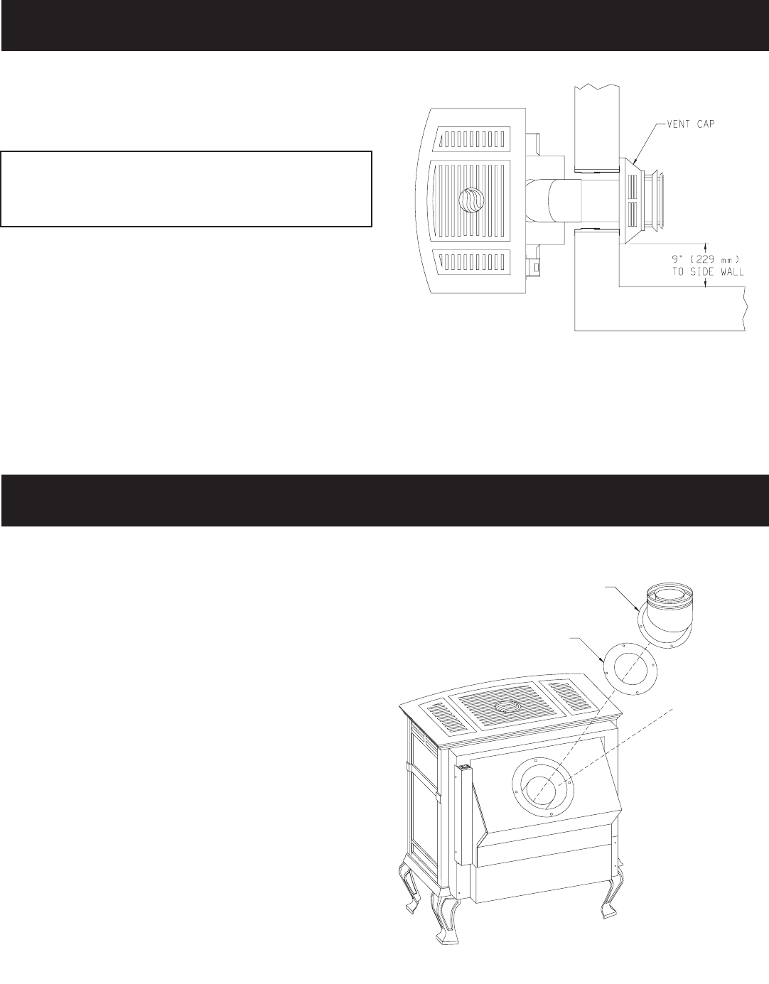
Cutting the Hole (Figure 18)
After the appliance has been positioned in its permanent location,
the hole through the exterior wall of the house can be cut. This
hole needs to be 10" high x 10" wide square with its center line
determined by the amount of vertical arise and horizontal run of the
termination. When locating the hole it must be noted that the bottom
of the cap must be 12" above the ground level, and top of the cap
must be no less than 18" below a combustible projection, and no
closer than 9" to any wall running parallel to vent termination.
Figure 18
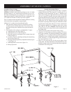
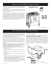
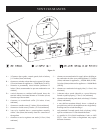
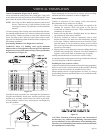
Attention: See Page 33 to order restrictor plate, part number CI-
235.
Figure 19
The restrictor plate is to be used only in a completely vertical vent
installation. The restrictor plate can be used when the vertical vent
rise is between 10 feet and 25 feet.
In a vertical vent rise the rear (yellow) flame on the main burner can
be reduced due to the drawing action from the flue exhaust pipe and
the air inlet pipe. A decrease in the height or the appearance of the
yellow flame may occur when the vertical vent rise is between 10
feet and 25 feet. To enhance the yellow flame on the main burner,
the restrictor plate can be installed beneath the vent elbow on the
appliance air drop.
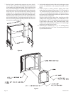
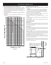
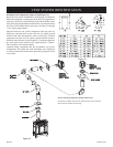
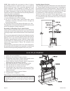
Please use the following steps to install the restrictor plate.
1. If attached, remove the vent pipe from the vent elbow on the
appliance.
2. Remove the vent elbow from the appliance air drop by removing
(4) 1/2" hex-head screws from vent elbow.
3. Align clearance holes on restrictor plate with screw holes on
appliance air drop. The gasket on the restrictor plate should
be positioned upward when the restrictor plate is placed onto
appliance air drop.
4. Align clearance holes on vent elbow with clearance holes on
restrictor plate and screw holes on appliance air drop.
5. Attach vent elbow and restrictor plate to appliance air drop.
Fasten (4) 1/2" hex-head screws from Step 2 through clearance
holes on vent elbow and restrictor plate and into screw holes
on appliance air drop.
Attention: Apply furnace cement to the top, exterior edge on
the cast iron flue outlet.
6. Installation of restrictor plate is completed.
VENTING FIREPLACE (continued)
RESTRICTOR PLATE INSTALLATION
RESTRICTOR PLATE
VENT ELBOW
APPL
Y FURNACE
CEMENT TO TOP,
EXTERIOR EDGE
ON CAST IRON
FLUE OUTLET