


15628-9-1007 Page 15
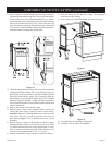
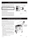
Attach black wire from REMOTE/OFF/ON switch to the front
1/4" male tab on the reset switch. Attachment of black wire onto
the reset switch is done in conjunction with the preceding steps for
Wire Channel Installation. Attach black wire on the back of the
reset switch to the TH/TP terminal on gas valve.
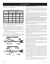
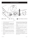
The reset switch can be activated if the main burner has a delayed
ignition. The right, relief door is connected by a metal wire to a
cotter pin that is inserted into the reset switch. When a delayed
ignition occurs the right, relief door pivots upward, the metal wire
pulls the cotter pin out of the reset switch and the main burner is
shut OFF.
Whenever the delayed ignition reset switch is activated you
must contact a qualified service person to determine the cause
for the delayed ignition reset switch to be activated.
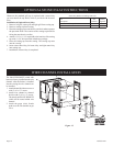
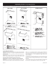
Replacement of cotter pin into delayed ignition reset switch assembly
by a qualified service person.
1. Lower valve cover.
2. The reset switch is located behind the left side of the valve
cover.
3. Verify the metal cable with attached cotter pin has free
movement.
4. Depress the metal lever arm located on the front of the reset
switch.
5. With the metal lever arm depressed, insert cotter pin into the
clearance hole on the right side of the bracket and into the
clearance hole on the left side of the bracket.
Attention: The tip of the cotter pin must remain flat. The tip of
the cotter pin must never be bent-over. If the tip of the cotter pin
is bent-over it could prevent the delayed ignition reset switch
from functioning during a delayed ignition.
6. Replacement of cotter pin into delayed ignition reset switch
assembly is completed.
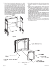
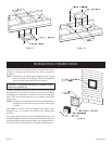
Reassembly and Resealing Gas Accumulation Relief System
(Relief Doors) and Combustion Chamber
Whenever the relief doors are pivoted open by a delayed ignition
in the main burner, the relief door gaskets and combustion chamber
must be examined by a qualified service person for damage. All
damaged gaskets on the relief doors and combustion chamber must
be replaced by a qualified service person. If damage occurs to the
combustion chamber, it must be replaced by a qualified service
person. Contact Empire Comfort Systems, Inc. for replacement
parts.
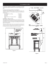
Figure 15
Figure 14
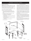
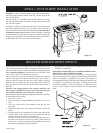
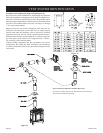
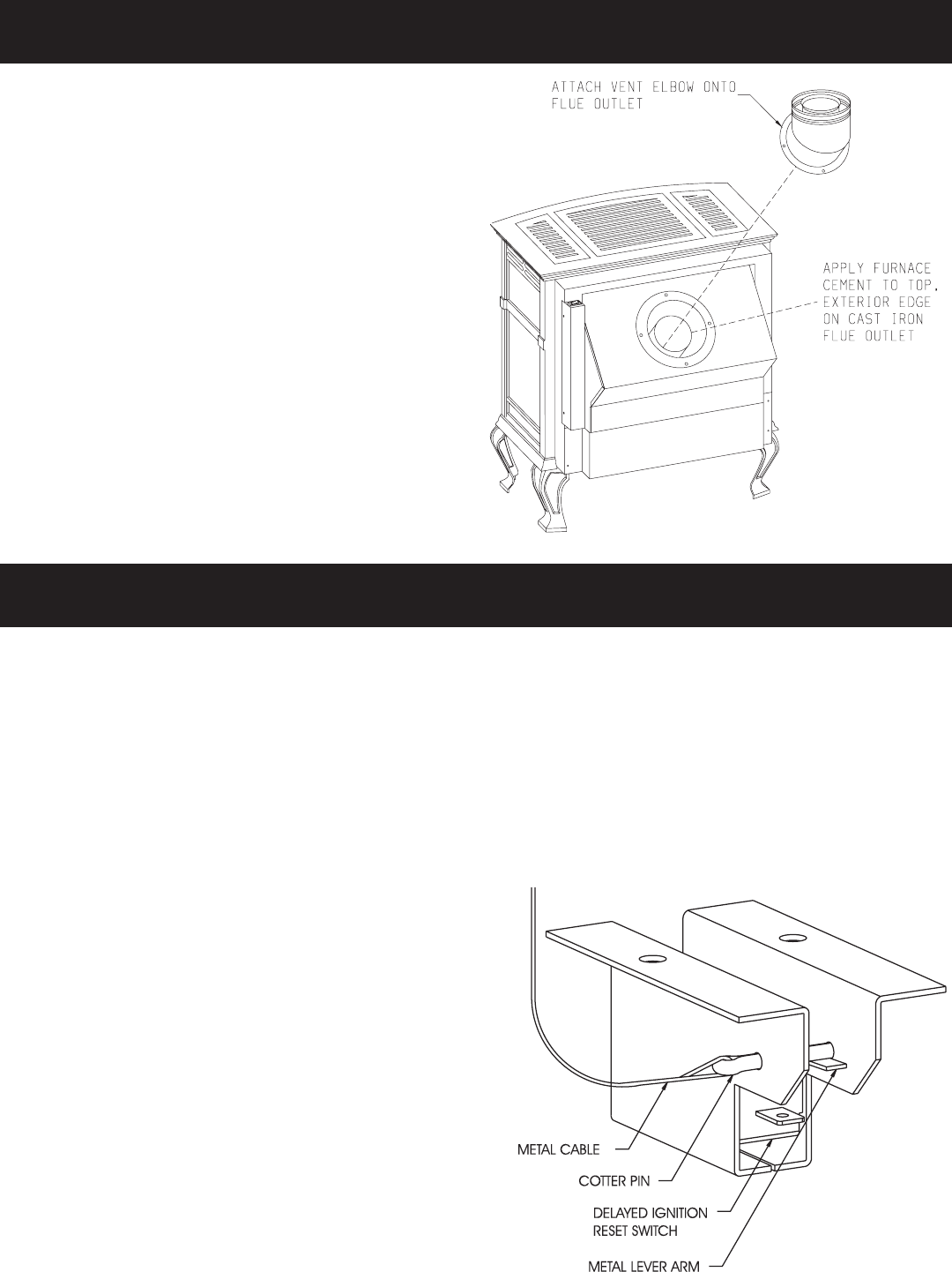
Attention: A tube of furnace cement is provided in the Owner's
Envelope. Apply furnace cement to the top, exterior edge on the
cast iron flue outlet.
Place the DVKA-1, vent elbow onto the flue outlet as you align
the clearance holes on the vent elbow with the clearance holes on
the vent elbow gasket.
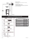
Install the vent elbow onto the flue outlet with (4) hex-head screws
provided in hardware package. The vent elbow can be installed in
the vertical position or horizontal position. All vent runs must have
a minimum vertical rise of two feet. If the vent elbow is installed
in the horizontal position and the vent run is directly behind the
fireplace, you must attach 36" snorkel Simpson Dura-Vent SD-981
or the Selkirk 4DT-ST36 on exterior of the structure.
DVKA-1 VENT ELBOW INSTALLATION
DELAYED IGNITION RESET SWITCH