


JOHNSON CONTROLS124
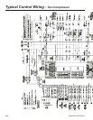
LEGEND
C.B. CIRCUIT BREAKER
D.E. DUAL ELEMENT FUSE
DISC SW DISCONNECT SWITCH
FACT CB FACTORY-MOUNTED CIRCUIT BREAKER
FLA FULL LOAD AMPS
HZ HERTZ
MAX MAXIMUM
MCA MINIMUM CIRCUIT AMPACITY
MIN MINIMUM
MIN NF MINIMUM NON-FUSED
RLA RATED LOAD AMPS
S.P. WIRE SINGLE-POINT WIRING
Electrical Notes
NOTES:
1. U.L. Label is provided on 50 and 60 Hz units for these electrical wiring congurations.
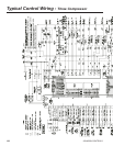
2. –– –– –– –– –– –– Dashed Line = Field Provided Wiring.
3. The above recommendations are based on the National Electric Code and using copper conductors only. Field wiring must also comply
with local codes. Group Rated breaker must be HACR type for cUL machines.
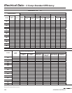
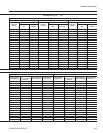
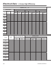
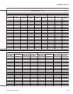
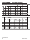
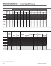
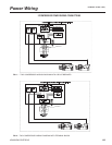
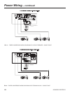
1. As standard, all units have single point power connection. Contact factory for information regarding dual
point power units.
2. Maximum Inverse Time Circuit Breaker or Dual Element Fuse - 225% of the largest compressor RLA
plus the sum of all other loads per NEC 440.22 (A).
3. MCA - Minimum Circuit Ampacity - 125% of the largest compressor RLA plus 100% of the remaining
compressor RLA's plus the sum of all condenser fan FLA's per NEC 440.33
4. Recommended time delay or dual element fuse size - 150%of the largest compressor RLA plus 100%
of the remaining compressor RLA's plus the sum of all condenser fan FLA's.
5. RLA - Rated Load Amps - rated in accordance with UL standard 1995.
6. Local codes may take precedence.
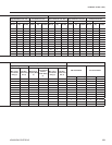
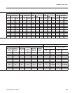
7. Control KVA includes operational controls and evaporator heaters.
8. System inrush current is less than RLA due to the use of York Variable Speed Drive technology. Typical
Compressor Starting Current ( rst four seconds of startup):
Rated Voltage Typical Starting Current per Compressor
380-400/50/3 28A
380/60/3 29A
460/60/3 23A
9. Voltage Utilization Range:
Rated Voltage Utilization Range
380-415/50/3 360 - 440
380/60/3 342 - 402
460/60/3 414 - 508