


JOHNSON CONTROLS
FORM 201.23-EG1 (1007)
135
with full height collars. Subcooling coil an
integral part of condenser. Design working
pressure shall be 450 PSIG (31 bar).
2. Low Sound Fans: Shall be dynamically and
statically balanced, direct drive, corrosion re-
sistant glass ber reinforced composite blades
molded into low noise, full airfoil cross section,
providing vertical air discharge from extended
orices. Guards of heavy gauge, PVC (polyvi-
nyl chloride) coated or galvanized steel.
3. Fan Motors: High efciency, direct drive, 3-
phase, insulation class “F”, current protected,
Totally Enclosed Air Over (TEAO), with double
sealed, permanently lubricated ball bear-
ings.
2.05 POWER AND ELECTRICAL REQUIREMENTS
A. Power/Control Panel:
1. NEMA 3R (IP55), powder painted steel cabi-
nets with hinged, latched, and gasket sealed
outer doors equipped with wind struts for safer
servicing. Provide main power connection(s),
compressor starters and fan motor contactors,
current overloads, and factory wiring.
2. Panel shall include control display access
door.
B. Single Point Power (As standard for 2 and 3 com-
pressor chillers)
1. Provide single point power connection to chill-
er, shall be 3 phase of scheduled voltage.
2. Terminal Block connections shall be provided
at the point of incoming single point connec-
tion.
C. Control Transformer: Power panel shall be supplied
with a factory mounted and wired control transformer
that will supply all unit control voltage from the main
unit power supply. Transformer shall utilize sched-
uled line voltage on the primary side and provide
115V/1Ø on secondary.
D. Short Circuit Withstand Rating of the chiller electrical
enclosure shall be (380, 400, & 460V: 65,000 Amps).
Rating shall be IAW UL508.
E. Motor Starters: Motors starters shall be reduced
inrush type (Wye-Delta or Solid State) for minimum
electrical inrush. Across the line type starters will
not be acceptable.
F. Power Factor:
1. Provide equipment with power factor correc-
tion capacitors as required to maintain a power
factor of 95% at all load conditions.
2. The installing contractor is responsible for ad-
ditional cost to furnish and install power factor
correction capacitors if they are not factory
mounted and wired.
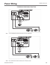
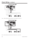
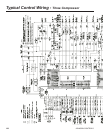
G. Exposed compressor and fan motor power wiring
shall be routed through liquid tight conduit.
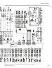
2.06 CONTROLS
A. General:
1. Provide automatic control of chiller operation
including compressor start/stop and load/un-
load, anti-recycle timers, condenser fans,
evaporator pump, evaporator heater, unit
alarm contacts and run signal contacts.
2. Chiller shall automatically reset to normal
chiller operation after power failure.
3. Unit operating software shall be stored in
non-volatile memory. Field programmed
set points shall be retained in lithium battery
backed regulated time clock (RTC) memory
for minimum 5 years.
4. Alarm contacts shall be provided to remote
alert for any unit or system safety fault.
B. Display and Keypad:
1. Provide minimum 80 character liquid crystal
display that is both viewable in direct sunlight
and has LED backlighting for nighttime view-
ing. Provide one keypad and display panel
per chiller.
2. Display and keypad shall be accessible
through display access door without opening
main control/electrical cabinet doors.
3. Display shall provide a minimum of unit
setpoints, status, electrical data, temperature
data, pressures, safety lockouts and diagnos-
tics without the use of a coded display.
4. Descriptions in English (or available language
options), numeric data in English (or Metric)
units.
5. Sealed keypad shall include unit On/Off
switch.
C. Programmable Setpoints (within Manufacturer limits):
display language; leaving chilled liquid temperature:
setpoint, control range; local or remote control; units
of measure; compressor lead/lag; and maximum
chilled water setpoint reset temperature range.
D. Display Data: Chiller liquid return and leaving temper-