


JOHNSON CONTROLS
FORM 201.23-EG1 (1007)
5
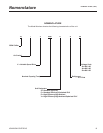
• Discharge line provided with manual compressor
shutoff service valve (See Options and Accessories for
suction line valve). Suction line equipped with closed-
cell insulation.
• Insulated external oil separators with no moving parts,
450 PSIG (31 bar) design working pressure, and UL
listing. Refrigerant system differential pressure pro-
vides oil ow through service replaceable, 0.5 micron,
full ow, cartridge type oil lter internal to compres-
sor.
• Oil cooling provided by dedicated air cooled nned
tube type heat exchanger located in the condenser
section of the machine.
• A ash tank is located in each refrigerant circuit to
increase the system efciency. The design working
pressure is 450 PSIG (31 bar).
• Suction lines, oil separators and ash tanks are cov-
ered with closed-cell insulation.
EVAPORATOR
• High efciency, direct-expansion type cooler with re
-
frigerant in tubes and chilled liquid through the bafed
shell. Independent circuits provided for each compres-
sor.
• Design working pressure of the shell waterside is 150
PSIG (10.3 bar), and 235 PSIG (16 bar) for the refrig-
erant side. Constructed and tested IAW applicable
sections of ASME Pressure Vessel Code, Section VIII,
Division (1). Water side exempt per paragraph U-1, ©,
(6).
• Removable heads allow access to internally-en-
hanced, seamless, copper tubes. Water vent and drain
connections included.
• The evaporator is equipped with a thermostatically
controlled heater for protection to -20°F (-29°C) am-
bient, and shell is covered with 3/4” (19mm), exible,
closed-cell insulation, thermal conductivity of 0.26k
(BTU/HR-Ft
2
-°F/in.) maximum.
• Water nozzles have grooves for mechanical (ANSI/
AWWA C-606) couplings, and shall be insulated by
Contractor after pipe installation. (See the Accessories
and Options section for ange options.
CONDENSER SECTION
• Condenser fans are dynamically and statically bal
-
anced, direct drive, corrosion resistant glass ber
reinforced composite blades molded into low noise,
full airfoil cross section, providing vertical air discharge
from extended orices. Guards of heavy gauge, PVC
(polyvinyl chloride) coated.
• Standard and reduced sound level models have
condensers tted with single speed fans. Low sound
models have two speed fans tted.
• The fan motors are the high efciency, direct drive, 6
pole on standard sound models and 8 pole on reduced
and low sound models, 3 phase, Class-“F”, current
overload protected, totally enclosed (TEAO) type with
double sealed, permanently lubricated, ball bearings
• Fin and tube condenser coils of seamless, internally
enhanced, high condensing coefcient, corrosion re-
sistant copper tubes arranged in staggered rows and
mechanically bonded to corrosion resistant aluminum
alloy ns with full height n collars. Design working
pressure is 450 PSIG (31 bar).
MICROPROCESSOR CONTROLS
• Microprocessor control system provides automatic
control of chiller operation including compressor start/
stop and load/unload, anti-recycle timers, condenser
fans, evaporator pump, evaporator heater, unit alarm
contacts and run signal contacts.
• Chiller automatically resets to normal chiller operation
after power failure.
• Unit operating software is stored in non-volatile
memory. Field programmed set points are retained
in lithium battery backed regulated time clock (RTC)
memory for minimum 5 years.
• Alarm contacts are provided to remote alert contacts
for any unit or system safety fault.
• Display and Keypad:
♦ 80 character liquid crystal display that is both view-
able in direct sunlight and has LED backlighting for
nighttime viewing. One keypad and display panel
is provided with every chiller.
♦ Display and keypad is accessible through display
access door without opening main control/electrical
cabinet doors.
♦ Display provides unit setpoints, status, electrical
data, temperature data, pressures, safety lock-
outs and diagnostics without the use of a coded
display.
♦ Descriptions in English (or available language op-
tions), numeric data in English (or Metric) units.
♦ Sealed keypad shall include unit On/Off switch.
• Programmable Setpoints (within Manufacturer limits):
display language; leaving chilled liquid temperature:
setpoint, control range; local or remote control; units of
measure; compressor lead/lag; and maximum chilled
water setpoint reset temperature range.
• Display Data: Chiller liquid return and leaving tempera-
tures, ambient, lead compressor identication, clock