


16
SERVICE (Cont.)
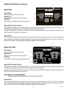
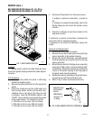
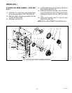
AC MOTOR AND GRIND CHAMBER
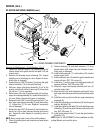
FIG. 3 AC MOTOR AND GRIND CHAMBER
P1704
Location:
The motor is located inside the upper part of the
grinder housing.
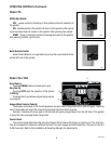
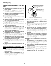
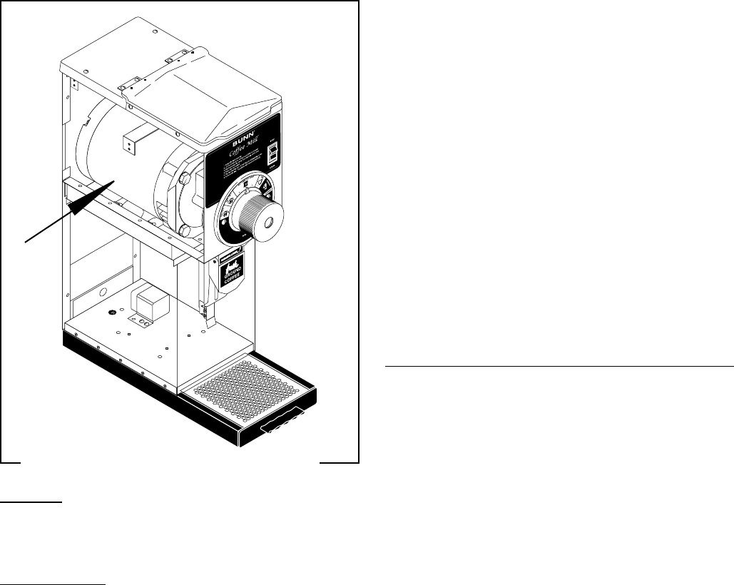
Test Procedure:
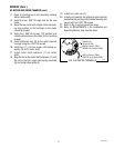
1. Remove the plug located on the right side of the
housing. Press the red “Reset” button visible
through the opening. Listen carefully for a “click”.
This resets the motor protection circuit and may
indicate that something other than coffee was
inserted into the hopper for grinding.
If the grinder remains unable to start, proceed to #2.
If the grinder stops operating shortly after starting, refer
to removal and replacement instructions and inspect
for foreign materials.
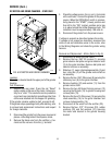
2. Disconnect the grinder from the power source and
place a coffee bag behind the dispense chute.
3. Remove the electrical access panel at the rear of
the motor.
4. Check the voltage across the white, red or red/
black and white/blue wires on terminals L1 & L2
with a voltmeter. Connect the grinder to the power
source. When the Off/On/Start switch is momen-
tarily placed in the “START” (lower) position and
then left in the “ON” (center) position and a bag
is in place behind the coffee dispense chute.
The indication must be:
a. 120 volts ac for two wire 120 volt models.
b. 230 volts ac for two wire 230 volt models
c. 240 volts ac for two wire 240 volt models.
5. Disconnect the grinder from the power source.
If voltage is present as described replace the motor.
If voltage is not present as described, reconnect the
white, red or red/black and white/blue wires to the mo-
tor, refer to the Wiring Diagrams and check the grinder
wiring harness.
Removal and Replacement - Motor (Refer to FIG.6):
1. Remove the plate on the rear of the motor and
disconnect all wires from the motor.
2. Remove the two .250”-20 screws (1) securing
grind selector dial plate and grind selector knob
(2) to the grind chamber. Remove dial plate and
selector knob as an assembly.
3. Slide burr (7), auger rotor/spring assembly (3),
shear plate (4) and burr rotor cup (5) off the
grinder motor shaft as an assembly.
4. Remove the two .250”-20 screws (8) securing the
stationary burr (9) to the grind chamber.
5. Remove bushing (10) and shaft extension (11)
from the grinder motor shaft.
6. Remove the two #8 thread forming screws (12)
securing the fill plate (13) to grinder housing and
remove plate (13).
7. Remove the four #10-24 screws (14) securing the
chute assembly (15) to the grind chamber and
remove chute assembly (15).
8. Remove the four .250”-20 screws, flat washer and
rubber washers securing the motor to the mount-
ing bracket.
9. Remove motor out the rear of the grinder hous-
ing.
10. Remove the four .250”-20 cage nuts from the
motor mount.
41545 122209